Bendix® WS-24™Wheel Speed Sensors
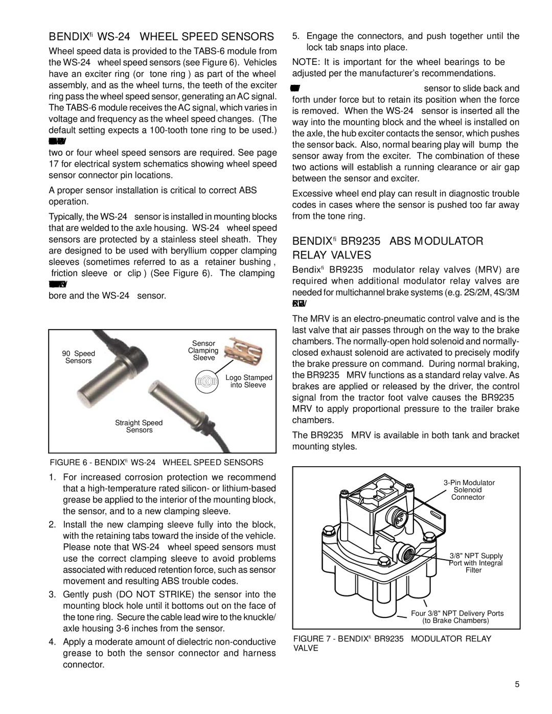
Wheel speed data is provided to the TABS-6 module from the WS-24™wheel speed sensors (see Figure 6). Vehicles have an exciter ring (or “tone ring”) as part of the wheel assembly, and as the wheel turns, the teeth of the exciter ring pass the wheel speed sensor, generating an AC signal. The TABS-6 module receives the AC signal, which varies in voltage and frequency as the wheel speed changes. (The default setting expects a 100-tooth tone ring to be used.) Vehicle axle and ABS control configurations determine if two or four wheel speed sensors are required. See page 17 for electrical system schematics showing wheel speed sensor connector pin locations.
A proper sensor installation is critical to correct ABS operation.
Typically, the WS-24™sensor is installed in mounting blocks that are welded to the axle housing. WS-24™wheel speed sensors are protected by a stainless steel sheath. They are designed to be used with beryllium copper clamping sleeves (sometimes referred to as a “retainer bushing”, “friction sleeve” or “clip”) (See Figure 6). The clamping sleeve provides a friction fit between the mounting block bore and the WS-24™sensor.
| | Sensor |
| 90° Speed | Clamping |
| Sleeve |
| Sensors |
| |
Logo Stamped
into Sleeve
Straight Speed
Sensors
FIGURE 6 - Bendix® WS-24™WHEEL SPEED SENSORS
1.For increased corrosion protection we recommend that a high-temperature rated silicon- or lithium-based grease be applied to the interior of the mounting block, the sensor, and to a new clamping sleeve.
2.Install the new clamping sleeve fully into the block, with the retaining tabs toward the inside of the vehicle. Please note that WS-24™wheel speed sensors must use the correct clamping sleeve to avoid problems associated with reduced retention force, such as sensor movement and resulting ABS trouble codes.
3.Gently push (DO NOT STRIKE) the sensor into the mounting block hole until it bottoms out on the face of the tone ring. Secure the cable lead wire to the knuckle/ axle housing 3-6 inches from the sensor.
4.Apply a moderate amount of dielectric non-conductive grease to both the sensor connector and harness connector.
5.Engage the connectors, and push together until the lock tab snaps into place.
NOTE: It is important for the wheel bearings to be adjusted per the manufacturer's recommendations.
The friction fit allows the WS-24™sensor to slide back and forth under force but to retain its position when the force is removed. When the WS-24™sensor is inserted all the way into the mounting block and the wheel is installed on the axle, the hub exciter contacts the sensor, which pushes the sensor back. Also, normal bearing play will “bump” the sensor away from the exciter. The combination of these two actions will establish a running clearance or air gap between the sensor and exciter.
Excessive wheel end play can result in diagnostic trouble codes in cases where the sensor is pushed too far away from the tone ring.
BENDIX® BR9235™ ABS Modulator Relay VALVES
Bendix® BR9235™ modulator relay valves (MRV) are required when additional modulator relay valves are needed for multichannel brake systems (e.g. 2S/2M, 4S/3M ABS configurations).
The MRV is an electro-pneumatic control valve and is the last valve that air passes through on the way to the brake chambers. The normally-open hold solenoid and normally- closed exhaust solenoid are activated to precisely modify the brake pressure on command. During normal braking, the BR9235™ MRV functions as a standard relay valve. As brakes are applied or released by the driver, the control signal from the tractor foot valve causes the BR9235™ MRV to apply proportional pressure to the trailer brake chambers.
The BR9235™ MRV is available in both tank and bracket mounting styles.
3-Pin Modulator
Solenoid
Connector
3/8" NPT Supply Port with Integral Filter
Four 3/8" NPT Delivery Ports
(to Brake Chambers)
FIGURE 7 - Bendix® BR9235™ Modulator relay valve

