Version Release 7.01 FW1.06p
BiGuard
iBusiness Security Gateway SMB User’s Manual
Disclaimer
Updated March 28 Copyright Information
BiGuard 30 User’s Manual
Trademarks
Safety Warnings
Chapter 2 Router Applications
Table of Contents Chapter 1 Introduction
1.3 Package Contents
1.1 Overview 1.2 Product Highlights
3.4 Configuring PCs for TCP/IP Networking
Chapter 4 Router Configuration
3.1 Overview 3.2 Before You Begin 3.3 Connecting Your Router
3.5 Factory Default Settings
4.4.2.1 ISP Settings
4.4 Configuration
4.3 Quick Start
4.4.2.2 Bandwidth Settings 4.4.2.3 WAN IP Alias
5.1 Basic Functionality
Chapter 5 Troubleshooting
4.5 Save Configuration To Flash 4.6 Logout
5.2 LAN Interface
5.6 Restoring Factory Defaults
Appendix A Product Specifications Appendix B Customer Support
5.4 ISP Connection 5.5 Problems with Date and Time
E.1 What is a VPN?
E.2.1 IPSec Security Components
E.2 What is IPSec?
E.2.1.1 Authentication Header AH
E.2.2 IPSec Modes
H.7 VPN Configuration
Appendix H Router Setup Examples
What is Quality of Service?
H.12 PPTP Remote Access by Windows XP
Chapter 1 Introduction
1.1 Overview
1.2 Product Highlights
BiGuard 30 iBusiness Security Gateway SMB
Power Status
WAN1 WAN2
1.3.2 Rear Panel
RESET WAN2 WAN1 LAN
1.3.4 Cabling
2.1 Overview
2.2 Bandwidth Management with QoS
2.2.1 QoS Technology
2.2.2 QoS Policies for Different Applications
VoIP Normal PCs Restricted PC
low network latencies to function properly. If bandwidth is being used by other applications such as an FTP server, users using VoIP will experience network lag and/or service interruptions during use. To avoid this scenario, this network has assigned VoIP with a guaranteed bandwidth and higher priority to ensure smooth communications. The FTP server, on the other hand, has been given a maximum bandwidth cap to make sure that regular service to both VoIP and normal Internet applications is uninterrupted
policies for different PCs on the network. Policy based traffic shaping lets you better manage your bandwidth, providing reliable Internet and network service to your organization
2.2.6 Management by IP or MAC address
2.2.7 DiffServ DSCP Marking
2.2.8 DSCP Matching
2.3.1 Outbound Fail Over
192.168.2.2
1st Connection
ISP 2nd connection
192.168.2.3
2.4.1 Inbound Fail Over
Before Fail Over
After Fail Over
2.4.2 Inbound Load Balancing
Remote Access from Internet
ISP ISP
2.5.1 DNS Inbound Fail Over
After Fail Over
Before Fail Over
Heavy load on WAN
DNS Request
DNS Reply
In the example above, the client is making a DNS request. The request is sent to the DNS server of BiGuard 30 through WAN2 1. WAN2 will route this request to the embedded DNS server of BiGuard 30 2. BiGuard 30 will analyze the bandwidth of both WAN1 and WAN2 and decide which WAN IP to reply to the request 3. After the decision is made, BiGuard 30 will route the DNS reply to the user through WAN2 4. The user will receive the DNS reply with the IP address of WAN1 5. The browser will initiate an HTTP request to the WAN1 IP address 6. The HTTP request will be send to BiGuard 30’s URL Host Map 7. The Host Map will then redirect the HTTP request to the HTTP server 8. The HTTP server will reply 9. The URL Host Map will route the packet through WAN1 to the user 10. Finally, the client will receive an HTTP reply packet
2.6.1 General VPN Setup
BiGuard Client
Before Fail Over
2.6.2 VPN Planning - Fail Over
Before Fail Over
BiGuard
3.1 Overview
3.2 Before You Begin
3.3 Connecting Your Router
3.4.1 Overview
3.4.2.1 Configuring 1. Select Start Settings Network Connections
3.4.2 Windows XP
3. Select Internet Protocol TCP/IP and click Properties
5. Click OK to finish the configuration
1. Click Start Programs Accessories Command Prompt
3.4.2.2 Verifying Settings
To verify your settings using a command prompt
2. In the Command Prompt window, type ipconfig and then press ENTER
To verify your settings using the Windows XP GUI
1. Click Start Settings Network Connections
An IP address between 192.168.1.1 and A subnet mask of
3. Click the Support tab
If you are using BiGuard 30’s default settings, your PC should
3.4.3.1 Configuring 1. Select Start Settings Control Panel
Have an IP address between 192.168.1.1 and Have a subnet mask of
Page
4. In the Local Area Connection window, click Properties
5. Select Internet Protocol TCP/IP and click Properties
Page
7. Click OK to finish the configuration
3.4.3.2 Verifying Settings
2. In the Command Prompt window, type ipconfig and then press ENTER
3.4.4.1 Installing Components
3.4.4 Windows 98 / Me
You must have the following installed
If you need to install a new Ethernet adapter, follow these steps
An Ethernet adapter TCP/IP protocol Client for Microsoft Networks
a. Click Add b. Select Adapter, then Add
If you need TCP/IP a. Click Add b. Select Protocol, then click Add
c. Select Microsoft. Æ TCP/IP, then OK
If you need Client for Microsoft Networks a. Click Add
3.4.4.2 Configuring 1. Select Start Settings Control Panel
b. Select Client, then click Add
3. Restart your PC to apply your changes
Page
Page
6. Click OK to apply the configuration
To check the TCP/IP configuration, use the winipcfg.exe utility
1. Select Start Run 2. Type winipcfg, and then click OK
3. From the drop-down box, select your Ethernet adapter
A default gateway of
Web Interface Username admin Password admin LAN Device IP Settings
IP Address Subnet Mask
WAN Port
IP address Subnet Mask
LAN Port
DHCP server function IP addresses for distribution to PCs
DHCP Static IP PPPoE PPTP Big Pond
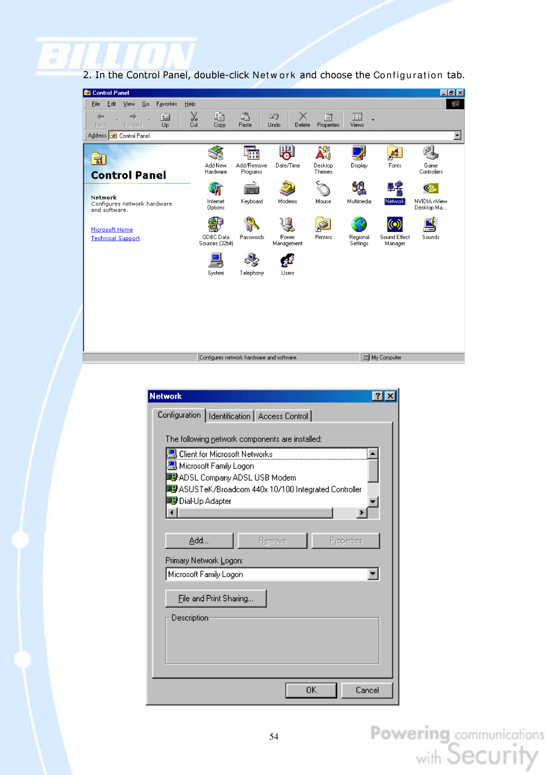
1. Select Start Settings Control Panel
2. Double-click the Network icon
4. Select Internet Protocol TCP/IP and click Properties
Page
server address automatically radio button
7. Click OK to save your changes
BiGuard 30 includes a Web Configuration Interface for easy administration via virtually any browser on your network. To access this interface, open your web browser, enter the IP address of your router, which by default is 192.168.1.254, and click Go. A user name and password window prompt will appear. Enter your user name and password the default user name and password are admin and admin to access the Web Configuration Interface
4.1 Overview
4.2 Status
4.2.1 ARP Table
4.2.2 Routing Table
Sessions
4.2.5 IPSec Status
4.2.6 PPTP Status
4.2.7 Traffic Statistics
4.2.8 System Log
4.2.9 IPSec Log
4.3.1 DHCP
4.3.2 Static IP
4.3.3 PPPoE
4.3.4 PPTP
4.3.5 Big Pond
4.4 Configuration
Subnet Mask Enter the subnet mask 255.255.255.0 by default
RIP RIP v2 Broadcast and RIP v2 Multicast. Check to enable RIP
Address Mapping 4.4.1.1 Ethernet
4.4.1.2 DHCP Server
4.4.1.3 LAN Address Mapping
WAN IP Alias
Please click Create to create a LAN Address Mapping rule
IP Alias 4.4.2.1 ISP Settings
4.4.2.1.1 DHCP
4.4.2.1.2 Static IP
4.4.2.1.3 PPPoE
4.4.2.1.4 PPTP Settings
4.4.2.1.5 Big Pond Settings
4.4.2.2 Bandwidth Settings
4.4.2.3 WAN IP Alias
4.4.3.1 General Settings
4.4.3.2 Outbound Load Balance
1. By session mechanism 2. By IP address hash mechanism
Choose one by clicking the corresponding radio button
4.4.3.3 Inbound Load Balance
Refresh Interval The interval refreshes are done. Denoted in seconds
Admin. Mail Box The administrator’s email account.e.gadmin@abc.com
Serial Number It is the version number that keeps in the SOA record
Retry Interval The interval retries are done. Denoted in seconds
Host URL The URL to be mapped
To add a host mapping URL to the list, click Create
Domain Name The domain name of the local host
Private IP Address The IP address of the local host
4.4.3.4 Protocol Binding
Destination IP Range
Interface Choose which WAN port to use WAN1, WAN2
Source IP Range All Source IP Click it to specify all source IPs
All Destination IP Click it to specify all source IPs
4.4.4.1 Time Zone
4.4.4.2 Remote Access
Allow Remote Access By
Only the PC Please specify the IP Address that is allowed to access
4.4.4.3 Firmware Upgrade
4.4.4.4 Backup / Restore
4.4.4.6 Password
4.4.4.5 Restart
Click Reset to reset to the default administration password admin
4.4.4.8 E-mail Alert
4.4.5.1 Packet Filter
When the entry is upper, the priority is higher
Source IP Select Any, Subnet, IP Range or Single Address
Destination IP Select Any, Subnet, IP Range or Single Address
4.4.5.2 URL Filter
URL Filtering You can choose to Enable or Disable this feature
Domains Filtering Click the top checkbox to enable this feature. You can also choose to disable all web traffic except for trusted sites by clicking the bottom checkbox. To edit the list of filtered domains, click Details
4.4.5.3 LAN MAC Filter
4.4.5.4 Block WAN Request
4.4.5.5 Intrusion Detection
You can find two items under the VPN section IPSec and PPTP
4.4.6.1.1 IPSec Wizard
Connection Name A user-defined name for the connection
Back Back to the Previous page Next Go to the next page
Back Back to the Previous page Next Go to the next page
Next Go to the next page
Done Click Done to apply the rule
Configuring a New VPN Connection
4.4.6.1.2 IPSec Policy
Connection Name A user-defined name for the connection
interface if Auto is selected
Any Local Address Will enable any local address on the network
DPD Setting DPD, Dead Peer Detection
Click Create to create a new PPTP VPN connection account
4.4.6.2 PPTP
Peer Encryption Mode Only Stateless or Allow Stateless and Stateful
4.4.7 QoS
WAN1 Outbound
Creating a New QoS Rule
Bandwidth Type
For IP Address
4.4.8 Virtual Server
For MAC Address
4.4.8.1 DMZ
4.4.8.2 Port Forwarding Table
4.4.9 Advanced
4.4.9.1 Static Route
4.4.9.2 Dynamic DNS
Wildcard Select this check box to enable the DYNDNS Wildcard
4.4.9.3 Device Management
Web Server Settings
SNMP Access Control
Device Name
SNMP V1 and
SNMP
4.4.9.4 IGMP
4.4.9.5 VLAN Bridge
4.5 Save Configuration To Flash
4.6 Logout
5.1.1 Router Won’t Turn On
5.1.2 LEDs Never Turn Off
5.1.3 LAN or Internet Port Not On
5.1.4 Forgot My Password
5.2.1 Can’t Access BiGuard 30 from the LAN
Check the corresponding LAN LEDs on your PC’s Ethernet device are on
4. Click OK under Internet Options to close the dialogue
If you only want to allow pop-up windows with your BiGuard
Disabling All Pop-ups
Enabling Pop-up Blockers with Exceptions
5.2.3.1 Pop-up Windows
4. Ensure that Scripting of Java applets is set to Enabled
5.4 ISP Connection
4. Click OK to close the dialogue
If an IP address cannot be obtained
5.5 Problems with Date and Time
If an IP address can be obtained, but your PC cannot load any web pages from the Internet
Appendix A Product Specifications
Availability and Resilience
Virtual Private Network
Network Protocols and Features
Content Filtering
Quality of Service Control
Firewall
Physical Interface
Physical Specifications
Power Requirement
Operating Environment
Appendix B Customer Support
Contact Billion
This device may not cause harmful interference
D.1.1.1 Net mask
D.1.1.2 Subnet Addressing
10.0.0.0 172.16.0.0 192.168.0.0
from these ranges
Routers can vary in performance and scale, the types of physical WAN connection they support, and the number of routing protocols supported. BiGuard 30 offers a convenient and powerful way for small-to-medium businesses to connect their networks
D.3.1.2 Denial of Service DoS Attack
D.3.1.1 Stateful Packet Inspection
With a LAN connected to the Internet through a router, there is a chance for hackers to access or disrupt your network. A simple NAT router provides a basic level of protection by shielding your network from the outside Internet. Still, there are ways for more dedicated hackers to either obtain information about your network or disrupt your network’s Internet access. Your BiGuard 30 provides an extra level of protection from such attacks with its built-in firewall
VPNs are traditionally used three ways
There are three major functions of IPSec
ESP divides its fields into three components…
SA is identified by 3 parameters
AH/E
TC Dat
E.2.3 Tunnel Mode AH
ESP Authentication
Quick Mode With PFS
Main Mode
Aggressive Mode
Quick Mode Without PFS
encryption algorithm, hash algorithm, and authentication method
F.1 IPSec Log Event Categories
F.2 IPSec Log Event Table
IKE Negotiate Packet Messages
Sending the first response message of aggressive mode. Done to
Sending the third message of main mode. Done for authentication
Received the third message of main mode. Done for authentication
Received the first response message of aggressive mode. Done to
Rejected IKE Messages
IKE Negotiated Status Messages
Received Delete SA payload Deleting ISAKMP State integer
Main/Aggressive mode peer ID is identifier string
ISAKMP SA Established IPsec SA Established
G.2 What is Quality of Service?
G.1 Overview
G.3 How Does QoS Work?
G.4 Who Needs QoS?
G.4.1 Home Users
Application
Data Ratio %
Priority
H.1 Outbound Fail Over
Page
H.2 Outbound Load Balancing
Step 2 Configure your WAN2 ISP settings and click Apply
Step 6 Click Save Config to save all changes to flash memory
H.3 Inbound Fail Over
General Settings. Select the Fail Over radio button
Step 2 Configure Fail Over options if necessary
Step 4 From the same menu, set the WAN2 DDNS settings
Step 5 Click Save Config to save all changes to flash memory
2 connection
H.4 DNS Inbound Fail Over
1st connection
2 nd connection
Enable radio button and configure DNS Server 1 by clicking Edit
Step 3 Input DNS Server 1 settings and click Apply
DNS Reply
H.5 DNS Inbound Load Balancing
DNS Request
200.200.200.1
Step 3 Go to Configuration Dual WAN Inbound Load Balance Host URL
Balance radio button
Mapping and configure your FTP mapping
Step 4 Next configure your HTTP mapping
H.6 Dynamic DNS Inbound Load Balancing
inbound and outbound bandwidth
Step 2 Go to Configuration Dual WAN General Settings and enable Load Balance mode. You may then decide whether to enable Service Detection or not
WAN1
Page
H.7.1 LAN to LAN
Local
Branch Office
Head Office
Remote
H.7.2 Host to LAN
Single client
Head Office
H.8 IP Sec Fail Over Gateway to Gateway
Proposal
Page
Page
Branch B
H.9 VPN Concentrator
Branch A
Headquarter
and configure the and configure the
H.10 Protocol Binding
Balancing radio button
Step 2 Go to Configuration Dual WAN Protocol Binding and configure settings for WAN1
Internet
H.11 Intrusion Detection
Internet
Hacker
Apply
Step2 Click Create to create a PPTP Account
Step3 Click Apply, you can see the account is successfully created
Step4 Click Save Config to save all changes to flash memory
Step5 In Windows XP, go Start Settings Network Connections
Step6 In Network Tasks, Click Create a new connection, and press Next
Step7 Select Connect to the network at my workplace and press Next
Step8 Select Virtual Private Network connection and press Next
Step9 Input the user-defined name for this connection and press Next
Step10 Input PPTP Server Address and press Next
Step11 Please press Finish
Step12 Double click the connection, and input Username and Password that defined in BiGuard PPTP Account Settings
200.200.200.1
Internet
Branch Office
BiGuard &PPTP Server
Step4 Click Save Config to save all changes to flash memory
Step6 Click Apply, and Save CONFIG