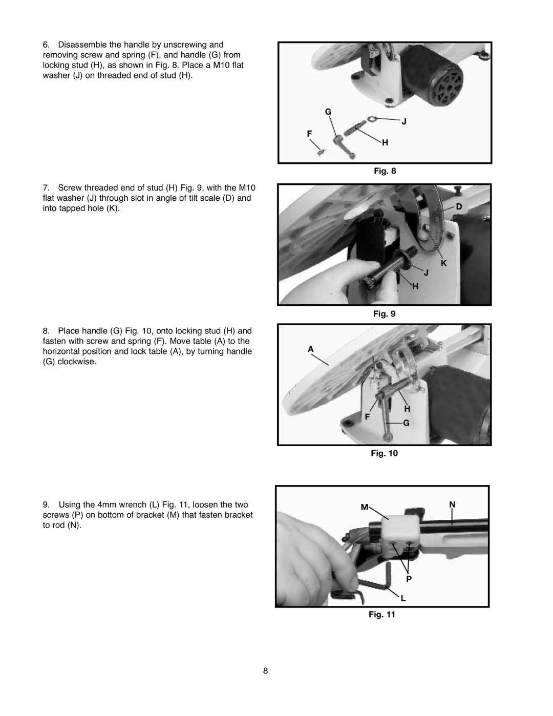
6.Disassemble the handle by unscrewing and removing screw and spring (F), and handle (G) from locking stud (H), as shown in Fig. 8. Place a M10 flat washer (J) on threaded end of stud (H).
7.Screw threaded end of stud (H) Fig. 9, with the M10 flat washer (J) through slot in angle of tilt scale (D) and into tapped hole (K).
G
![]() J
J
F
H
Fig. 8
![]() D
D
K
J
H
Fig. 9
8.Place handle (G) Fig. 10, onto locking stud (H) and fasten with screw and spring (F). Move table (A) to the horizontal position and lock table (A), by turning handle
(G) clockwise.
A
F
H
G
9.Using the 4mm wrench (L) Fig. 11, loosen the two screws (P) on bottom of bracket (M) that fasten bracket to rod (N).
Fig. 10
MN
P
L
Fig. 11
8