1.Remove the blade from the scroll saw.
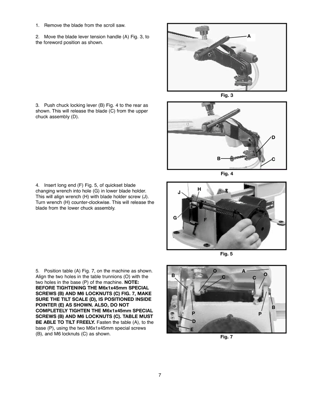
2.Move the blade lever tension handle (A) Fig. 3, to the foreword position as shown.
3.Push chuck locking lever (B) Fig. 4 to the rear as shown. This will release the blade (C) from the upper chuck assembly (D).
4.Insert long end (F) Fig. 5, of quickset blade changing wrench into hole (G) in lower blade holder. This will align wrench (H) with blade holder screw (J). Turn wrench (H)
J ![]()
![]() A
A
Fig. 3
D
BC
Fig. 4
H
5.Position table (A) Fig. 7, on the machine as shown. Align the two holes in the table trunnions (O) with the two holes in the base (P) of the machine. NOTE:
BEFORE TIGHTENING THE M6x1x45mm SPECIAL SCREWS (B) AND M6 LOCKNUTS (C) FIG. 7, MAKE SURE THE TILT SCALE (D), IS POSITIONED INSIDE POINTER (E) AS SHOWN. ALSO, DO NOT COMPLETELY TIGHTEN THE M6x1x45mm SPECIAL SCREWS (B) AND M6 LOCKNUTS (C). TABLE MUST BE ABLE TO TILT FREELY. Fasten the table (A), to the base (P), using the two M6x1x45mm special screws (B), and M6 locknuts (C) as shown.
GF
Fig. 5
O A ![]()
B  CC O
CC O
B
PP
D
E
Fig. 7
7