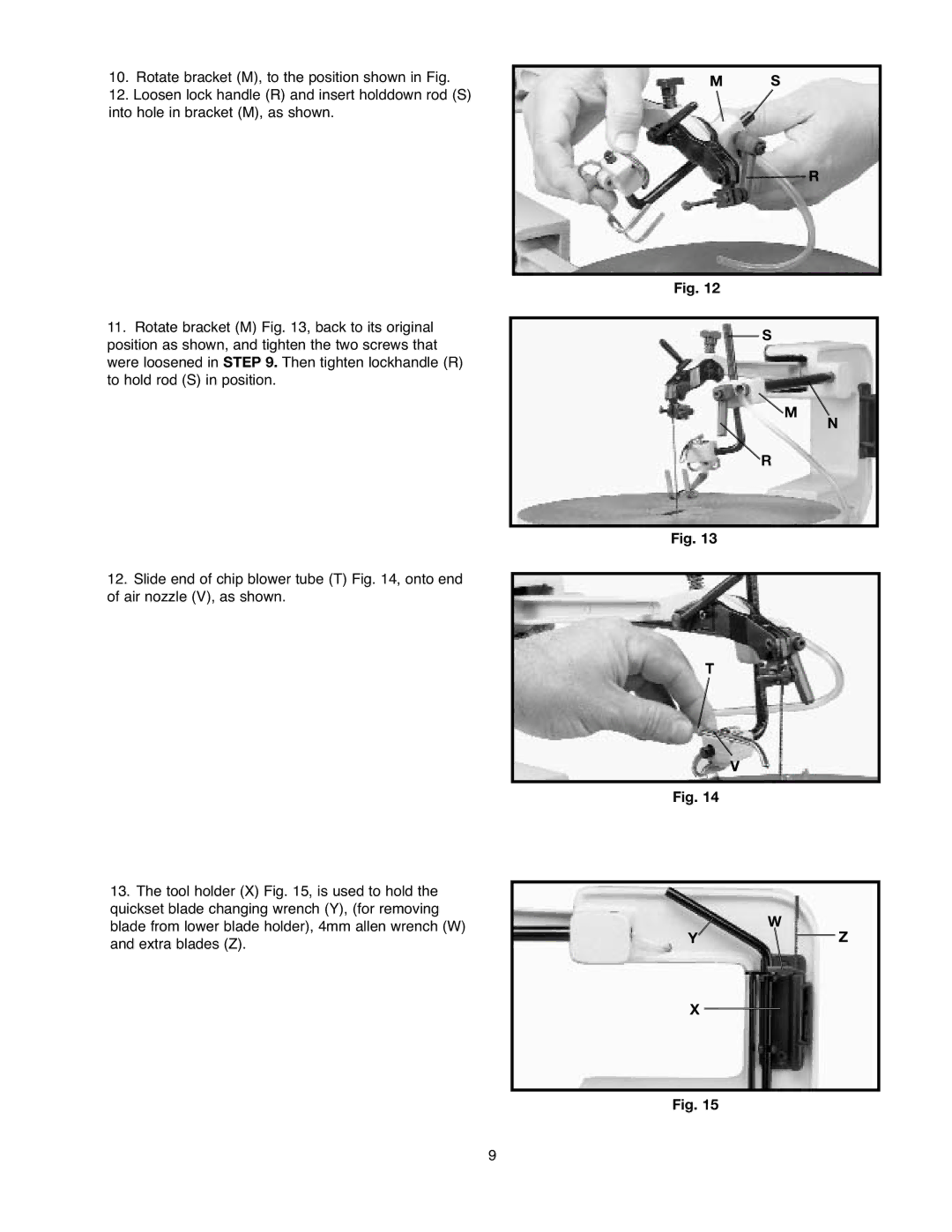
10.Rotate bracket (M), to the position shown in Fig.
12.Loosen lock handle (R) and insert holddown rod (S) into hole in bracket (M), as shown.
11.Rotate bracket (M) Fig. 13, back to its original position as shown, and tighten the two screws that were loosened in STEP 9. Then tighten lockhandle (R) to hold rod (S) in position.
12.Slide end of chip blower tube (T) Fig. 14, onto end of air nozzle (V), as shown.
13.The tool holder (X) Fig. 15, is used to hold the quickset blade changing wrench (Y), (for removing blade from lower blade holder), 4mm allen wrench (W) and extra blades (Z).
M S
R
Fig. 12
S
![]() M
M
N
R
Fig. 13
T
V
Fig. 14
W
YZ
X
Fig. 15
9