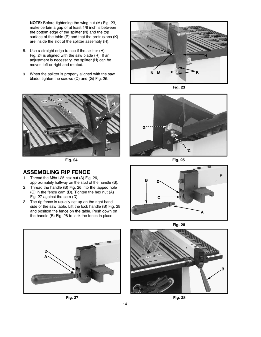
NOTE: Before tightening the wing nut (M) Fig. 23, make certain a gap of at least 1/8 inch is between the bottom edge of the splitter (N) and the top surface of the table (P) and that the protrusions (K) are inside the slot of the splitter assembly (H).
8.Use a straight edge to see if the splitter (H) Fig. 24 is aligned with the saw blade (R). If an adjustment is necessary, the splitter (H) can be moved left or right and rotated.
9.When the splitter is properly aligned with the saw blade, tighten the screws (C) and (G) Fig. 25.
R
H
Fig. 24
ASSEMBLING RIP FENCE
1.Thread the M8x1.25 hex nut (A) Fig. 26, approximately halfway on the stud of the handle (B).
2.Thread the handle (B) Fig. 26 into the tapped hole
(C)in the fence cam (D). Tighten the hex nut (A) Fig. 27 against the cam (D).
3.The rip fence is usually set up on the right hand side of the saw table. Lift the lock handle (B) Fig. 28 and position the fence on the table. Push down on the handle (B) Fig. 28 to lock the fence in place.
D
A
Fig. 27
P![]()
![]() H
H
NM![]()
![]() K
K
Fig. 23
G ![]()
![]()
C
Fig. 25
BD
C ![]()
A
Fig. 26
B
Fig. 28
14