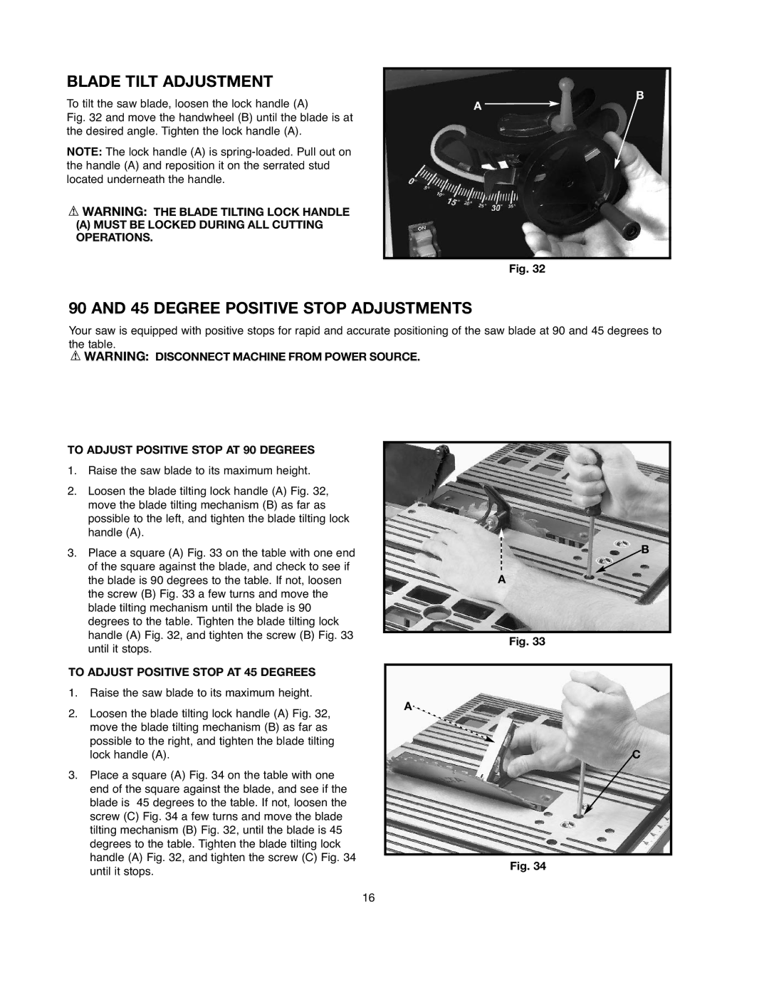
BLADE TILT ADJUSTMENT
To tilt the saw blade, loosen the lock handle (A)
Fig. 32 and move the handwheel (B) until the blade is at the desired angle. Tighten the lock handle (A).
NOTE: The lock handle (A) is
![]() WARNING: THE BLADE TILTING LOCK HANDLE
WARNING: THE BLADE TILTING LOCK HANDLE
(A)MUST BE LOCKED DURING ALL CUTTING OPERATIONS.
B
A ![]()
Fig. 32
90 AND 45 DEGREE POSITIVE STOP ADJUSTMENTS
Your saw is equipped with positive stops for rapid and accurate positioning of the saw blade at 90 and 45 degrees to the table.
![]() WARNING: DISCONNECT MACHINE FROM POWER SOURCE.
WARNING: DISCONNECT MACHINE FROM POWER SOURCE.
TO ADJUST POSITIVE STOP AT 90 DEGREES
1.Raise the saw blade to its maximum height.
2.Loosen the blade tilting lock handle (A) Fig. 32,
move the blade tilting mechanism (B) as far as possible to the left, and tighten the blade tilting lock handle (A).
3. Place a square (A) Fig. 33 on the table with one end | B | |
| ||
of the square against the blade, and check to see if | A | |
the blade is 90 degrees to the table. If not, loosen | ||
the screw (B) Fig. 33 a few turns and move the |
| |
blade tilting mechanism until the blade is 90 |
| |
degrees to the table. Tighten the blade tilting lock |
| |
handle (A) Fig. 32, and tighten the screw (B) Fig. 33 |
| |
Fig. 33 | ||
until it stops. | ||
| ||
TO ADJUST POSITIVE STOP AT 45 DEGREES |
| |
|
1.Raise the saw blade to its maximum height.
2. Loosen the blade tilting lock handle (A) Fig. 32, | A |
| |
move the blade tilting mechanism (B) as far as |
|
possible to the right, and tighten the blade tilting |
|
lock handle (A). | C |
3. Place a square (A) Fig. 34 on the table with one |
| |
end of the square against the blade, and see if the |
| |
blade is 45 degrees to the table. If not, loosen the |
| |
screw (C) Fig. 34 a few turns and move the blade |
| |
tilting mechanism (B) Fig. 32, until the blade is 45 |
| |
degrees to the table. Tighten the blade tilting lock |
| |
handle (A) Fig. 32, and tighten the screw (C) Fig. 34 | Fig. 34 | |
until it stops. | ||
|
16