ATTACHING BLADE HEIGHT ADJUSTING HANDWHEEL
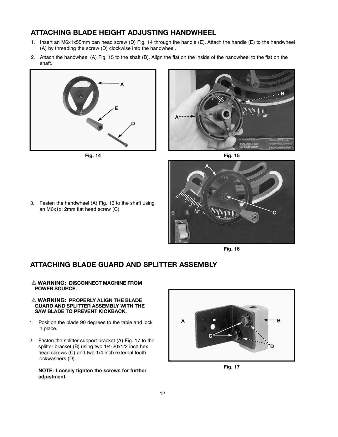
1.Insert an M6x1x55mm pan head screw (D) Fig. 14 through the handle (E). Attach the handle (E) to the handwheel
(A) by threading the screw (D) clockwise into the handwheel.
2.Attach the handwheel (A) Fig. 15 to the shaft (B). Align the flat on the inside of the handwheel to the flat on the shaft.
![]() A
A
![]() E
E
D
Fig. 14
![]() B
B
A ![]()
![]()
Fig. 15
A
3.Fasten the handwheel (A) Fig. 16 to the shaft using an M6x1x12mm flat head screw (C)
C
Fig. 16
ATTACHING BLADE GUARD AND SPLITTER ASSEMBLY
![]() WARNING: DISCONNECT MACHINE FROM POWER SOURCE.
WARNING: DISCONNECT MACHINE FROM POWER SOURCE.
![]() WARNING: PROPERLY ALIGN THE BLADE GUARD AND SPLITTER ASSEMBLY WITH THE SAW BLADE TO PREVENT KICKBACK.
WARNING: PROPERLY ALIGN THE BLADE GUARD AND SPLITTER ASSEMBLY WITH THE SAW BLADE TO PREVENT KICKBACK.
1.Position the blade 90 degrees to the table and lock in place.
2.Fasten the splitter support bracket (A) Fig. 17 to the splitter bracket (B) using two
NOTE: Loosely tighten the screws for further adjustment.
A![]()
![]() B
B
C ![]()
D
Fig. 17
12