PREPARATION |
|
|
PLEASE REFER TO DIAGRAMS (A, B, C...) AND ITEM NUMBERS (1, 2, 3...) AS NOTED THROUGHOUT MANUAL. FOR EXAMPLE, | ||
| ||
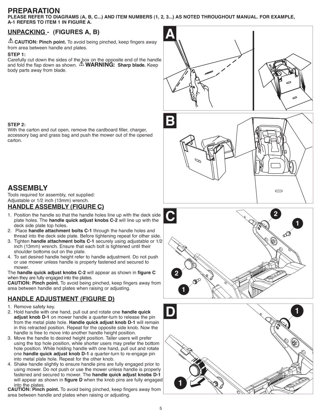
UNPACKING - (FIGURES A, B) |
| |
CAUTION: Pinch point. To avoid being pinched, keep fingers away | ||
from area between handle and plates. |
| |
STEP 1: |
|
|
Carefully cut down the sides of the box on the opposite end of the handle | ||
and fold the flap down as shown. | WARNING: | Sharp blade. Keep |
body parts away from blade. |
|
|
WithSTEPthe2: carton end cut open, remove the cardboard filler, charger, | B |
|
accessory bag and grass bag and push the mower out of the opened |
|
|
carton. |
|
|
ASSEMBLY |
|
|
Tools required for assembly, not supplied: |
|
|
Adjustable or 1/2 inch (13mm) wrench. |
|
|
HANDLE ASSEMBLY(FIGURE C) | 2 |
|
1. Position the handle so that the handle holes line up with the deck side | 1 | |
plate holes. The handle quick adjust knobs |
| |
deck side plate top holes. |
| |
2. Place handle attachment bolts |
|
|
thread into the deck side plate. Before tightening repeat for other side. |
|
|
3. Tighten handle attachment bolts |
|
|
inch (13mm) wrench. Ensure that each bolt is tightened until their |
|
|
shoulder bottoms out on the plate. |
|
|
4. To set desired handle height refer to handle adjustment. Do not push |
|
|
or use mower unless handle is properly fastened and secured to |
|
|
mower. | 2 |
|
The handle quick adjust knobs |
| |
when they are fully engaged into the plates. |
| |
CAUTION: Pinch point. To avoid being pinched, keep fingers away from | 1 |
|
area between handle and plates when raising or adjusting. |
| |
HANDLE ADJUSTMENT (FIGURE D) |
| |
1. Remove safety key. |
| 1 |
2. Hold handle with one hand, pull out and rotate one handle quick |
| |
adjust knob |
|
|
from the metal plate hole. Handle quick adjust knob |
|
|
in this retracted position. Repeat for the opposite side knob. Now the |
|
|
handle is free to move into another handle height position. |
|
|
3. Move the handle to desired height position. Taller users will prefer |
|
|
using the top hole position, while shorter users may prefer the bottom |
|
|
hole position. While holding handle with one hand, pull out and rotate |
|
|
one handle quick adjust knob |
|
|
into metal plate hole. Repeat for the other knob. |
|
|
4. Shake handle slightly to ensure handle pins are fully engaged prior to |
|
|
using mower. Do not push or use the mower unless handle is properly |
|
|
fastened and secured to mower. The handle quick adjust knobs |
|
|
will appear as shown in figure D when the knob pins are fully engaged | 1 |
|
into the plates. |
| |
CAUTION: Pinch point. To avoid being pinched, keep fingers away from |
|
|
area between handle and plates when raising or adjusting. |
|
|
5