ASSEMBLY INSTRUCTIONS
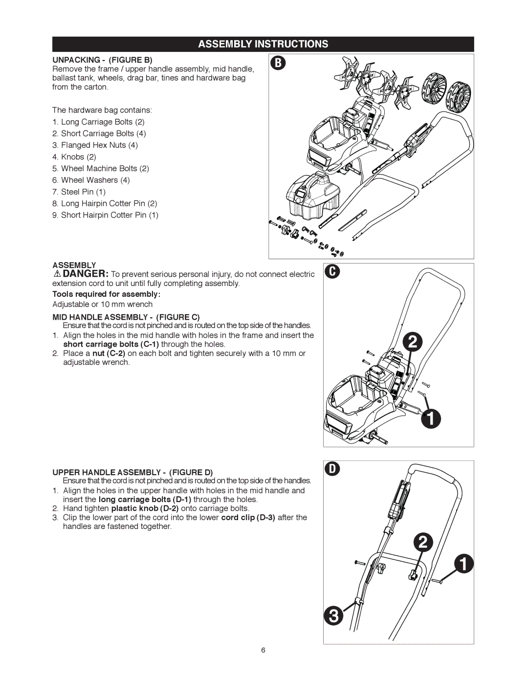
UNPACKING - (FIGURE B)
Remove the frame / upper handle assembly, mid handle, ballast tank, wheels, drag bar, tines and hardware bag from the carton.
The hardware bag contains:
1.Long Carriage Bolts (2)
2.Short Carriage Bolts (4)
3.Flanged Hex Nuts (4)
4.Knobs (2)
5.Wheel Machine Bolts (2)
6.Wheel Washers (4)
7.Steel Pin (1)
8.Long Hairpin Cotter Pin (2)
9.Short Hairpin Cotter Pin (1)
B |
ASSEMBLY
![]() DANGER: To prevent serious personal injury, do not connect electric extension cord to unit until fully completing assembly.
DANGER: To prevent serious personal injury, do not connect electric extension cord to unit until fully completing assembly.
Tools required for assembly:
Adjustable or 10 mm wrench
MID HANDLE ASSEMBLY - (FIGURE C)
Ensure that the cord is not pinched and is routed on the top side of the handles.
1.Align the holes in the mid handle with holes in the frame and insert the short carriage bolts
2.Place a nut
UPPER HANDLE ASSEMBLY - (FIGURE D)
Ensure that the cord is not pinched and is routed on the top side of the handles.
1.Align the holes in the upper handle with holes in the mid handle and insert the long carriage bolts
2.Hand tighten plastic knob
3.Clip the lower part of the cord into the lower cord clip
C |
D |
3 ![]()
6