Chapter 3: Hardware Installation
Figure 3-4. USB cable connected to PoE Gigabit Injector.
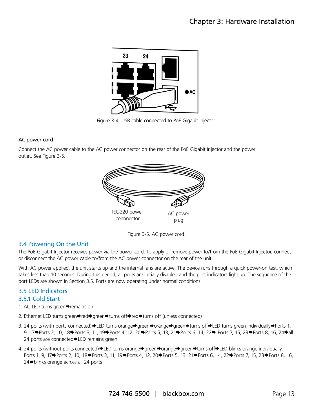
AC power cord
Connect the AC power cable to the AC power connector on the rear of the PoE Gigabit Injector and the power outlet. See Figure 3-5.
AC power | ||
connnector | ||
plug | ||
|
Figure 3-5. AC power cord.
3.4 Powering On the Unit
The PoE Gigabit Injector receives power via the power cord. To apply or remove power to/from the PoE Gigabit Injector, connect or disconnect the AC power cable to/from the AC power connector on the rear of the unit.
With AC power applied, the unit starts up and the internal fans are active. The device runs through a quick
3.5LED Indicators 3.5.1 Cold Start
1.AC LED turns greenÆremains on
2.Ethernet LED turns greenÆredÆgreenÆturns offÆredÆturns off (unless connected)
3.24 ports (with ports connected)ÆLED turns orangeÆgreenÆorangeÆgreenÆturns offÆLED turns green individuallyÆPorts 1, 9, 17ÆPorts 2, 10, 18ÆPorts 3, 11, 19ÆPorts 4, 12, 20ÆPorts 5, 13, 21ÆPorts 6, 14, 22Æ Ports 7, 15, 23ÆPorts 8, 16, 24Æall 24 ports are connectedÆLED remains green
4.24 ports (without ports connected)ÆLED turns orangeÆgreenÆorangeÆgreenÆturns offÆLED blinks orange individually Ports 1, 9, 17ÆPorts 2, 10, 18ÆPorts 3, 11, 19ÆPorts 4, 12, 20ÆPorts 5, 13, 21ÆPorts 6, 14, 22ÆPorts 7, 15, 23ÆPorts 8, 16, 24Æblinks orange across all 24 ports
Page 13 |