Installation Procedure
SW2 - P2 LOOPBACK “P2-LB”
When this DIP-switch is in the DOWN position (factory default), port P2 loopback is disabled. When this DIP-switch is in the UP “P2-LB” position, loopback is enabled on port P2. When enabled, all data received on port P2 is transmitted out port P2 and the connection between port P2 and port P1 is interrupted.
NOTE: For the XFP model, simultaneous loopback of port P1 and port P2 requires the XFP transceiver to support lineside loopback capability.
SW3 - P2 Short Range
When this DIP-switch is in the DOWN position (factory default), port P2 short range feature is disabled. When disabled, port P2 will support up to 100 meters of CAT 6A cabling. When this DIP-switch is in the UP “P2-SR” position, port P2 will support up to 30 meters of CAT 6A or better cabling in a reduced power consumption mode.
SW4 - P1 BIST (SFP+ Model Only)
When this DIP-switch is in the DOWN position (factory default), port P1 Built-In Self Test is disabled. When this DIP-switch is in the UP “P1-Tst” position, the port will transmit a Pseudo Random Bit Sequence (PRBS).
When two XGT+ converters are connected via port P1 (Port 1 to Port 1), the BIST function is supported. The XGT+ initiating BIST (DIP-switch SW4 UP) will generate and send a PRBS pattern out Port 1 to the other module. The receiving XGT+ will detect a good test pattern and return a PRBS acknowledgement test pattern back to the initiating XGT+.
A successful test will produce a green blinking (5Hz) P1 LB LED on the initiating XGT+ and a green blinking (1Hz) P1 LB LED on the receiving XGT+. If the initiating XGT+ does not receive a valid response, the P1 LB LED will be blinking amber (5Hz). When BIST is initiated, the traffic received on Port 2 of both converters will be discarded.
If loopback has been initiated, the self diagnostic circuit test DIP-switch will be ignored. If self diagnostic circuit test has been initiated, the loopback DIP-switches will be ignored.
DIP-SWITCH BANK 2
LINK MODES
SW1 and SW2 - LINK MODES
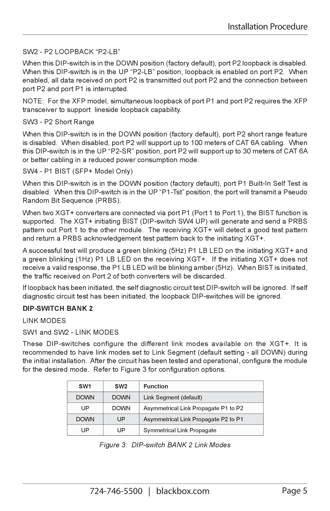
These DIP-switches configure the different link modes available on the XGT+. It is recommended to have link modes set to Link Segment (default setting - all DOWN) during the initial installation. After the circuit has been tested and operational, configure the module for the desired mode. Refer to Figure 3 for configuration options.
SW1 | SW2 | Function |
DOWN | DOWN | Link Segment (default) |
| | |
UP | DOWN | Asymmetrical Link Propagate P1 to P2 |
| | |
DOWN | UP | Asymmetrical Link Propagate P2 to P1 |
| | |
UP | UP | Symmetrical Link Propagate |
| | |
Figure 3: DIP-switch BANK 2 Link Modes