Installation
Oven Assembly
DOOR RELOCATION
The
1.Shut off the oven power switch.
2.Remove the door as follows:
a.) Loosen the two upper door bolts.
b.) Loosen the two lower door bolts. Remove the top bolt.
c.) Slide the remaining lower door bolt up in its slotted hole.
NOTE: The lower door pin attached to the bolt will release from the bushing in the unit frame.
d.) Tilt the door (with the 5/16” thick washer) away from the unit.
e.) Lower the door so that the upper door pin drops out of the bushing in the unit frame.
3. Relocate the hinge and catch parts as follows:
a.) Remove the trim plates located on the frame opposite the door pins. The two plates are attached with one screw each.
NOTE: This will expose the pin/bushing holes for the alternate door loca- tion.
b.) Move the two brass door bushings in the unit frame to the alternate door pin/bush- ing holes.
c.) Attach the trim plates to the frame over the two holes where the bushings were. Mounting holes are provided at the new locations.
NOTE: Note that the upper trim plate has a slotted air opening.
d.) Move the door catch plate located on the upper door frame to the opposite side of the oven cavity. Mounting holes are pro- vided at the new location for the catch plate (two screws).
4. Reattach the door as follows:
a.) Attach the door to the unit at the relocated bushings by reversing the steps above.
b.) Tighten the four door bolts hand tight only.
5.Relocate the handle and plate assembly on the door as follows:
a.) Remove the four hex head screws which attach the handle plates to the door.
b.) Twist the upper plate around the door handle by at least 90_.
c.) Lower the handle and plate assembly out of the door.
d.) Flip the handle and plate assembly 180_.
e.) Reattach the assembly by inserting the roller latch plate into the opening at the door top.
f.) Twist the lower plate around the door han- dle to its original mounting position.
g.) Reinstall the four screws through the han- dle plate into the door.
6.Adjust the door as follows:
a.) Close the door and check that the roller latch secures the door tightly.
b.) Adjust the catch plate (by its slotted mounting holes) if necessary.
7.Turn the unit on and verify that the door prox- imity switch shuts off the fan when the door opens.
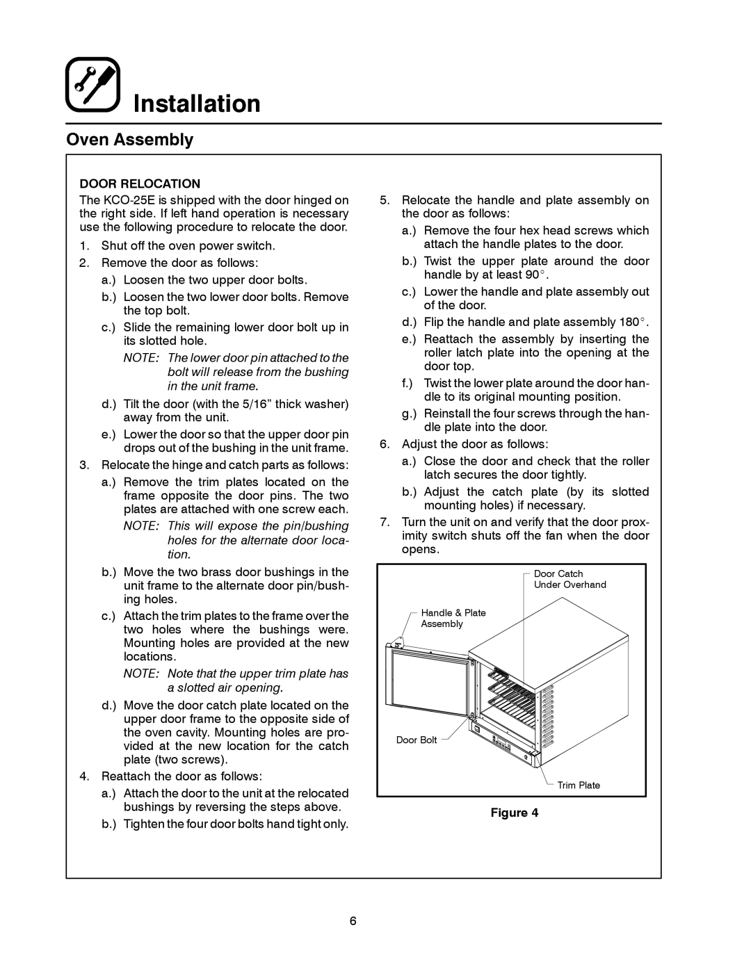
Door Catch |
Under Overhand |
Handle & Plate |
Assembly |
Door Bolt |
Trim Plate |
Figure 4
6