Optional Installation (continued) | P12 |
7521 AND 7522 BATTERY CHARGERS |
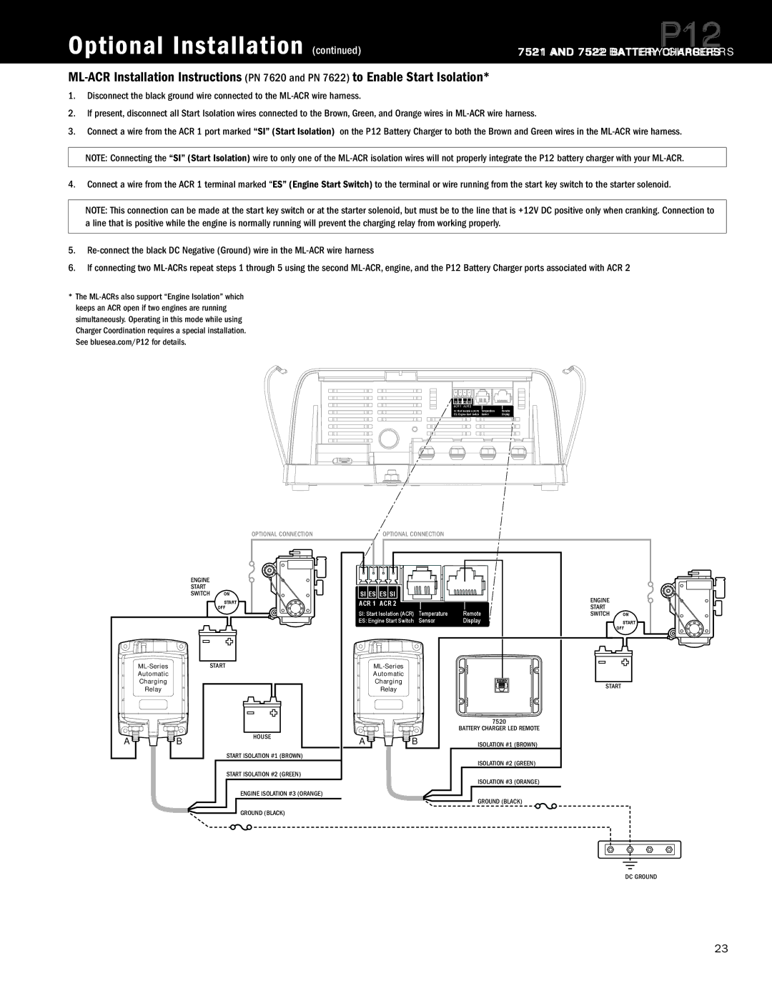
1.Disconnect the black ground wire connected to the
2.If present, disconnect all Start Isolation wires connected to the Brown, Green, and Orange wires in
3.Connect a wire from the ACR 1 port marked “SI” (Start Isolation) on the P12 Battery Charger to both the Brown and Green wires in the
NOTE: Connecting the “SI” (Start Isolation) wire to only one of the
4.Connect a wire from the ACR 1 terminal marked “ES” (Engine Start Switch) to the terminal or wire running from the start key switch to the starter solenoid.
NOTE: This connection can be made at the start key switch or at the starter solenoid, but must be to the line that is +12V DC positive only when cranking. Connection to a line that is positive while the engine is normally running will prevent the charging relay from working properly.
5.
6.If connecting two
*The
SI ES | ES SI |
|
|
ACR 1 | ACR 2 |
|
|
SI: Start Isolation (ACR) | Temperature | Remote | |
ES: Engine Start Switch | Sensor | Display | |
OPTIONAL CONNECTION
| ENGINE |
|
| START |
|
| SWITCH | ON |
|
| START |
|
| OFF |
START | ||
Automatic |
|
|
Charging |
|
|
Relay |
|
|
A | B | HOUSE |
| ||
|
| START ISOLATION #1 (BROWN) |
START ISOLATION #2 (GREEN)
ENGINE ISOLATION #3 (ORANGE)
GROUND (BLACK)
OPTIONAL CONNECTION
SI ES | ES SI |
|
| ENGINE |
|
ACR 1 | ACR 2 |
|
|
| |
SI: Start Isolation (ACR) | Temperature | Remote | START |
| |
SWITCH | ON | ||||
ES: Engine Start Switch | Sensor | Display |
| START | |
|
|
|
|
| OFF |
|
|
|
| ||
Automatic |
|
|
|
| |
Charging |
|
| START | ||
| Relay |
|
| ||
|
|
|
|
| |
|
|
| 7520 |
|
|
|
|
| BATTERY CHARGER LED REMOTE |
|
|
A | B |
| ISOLATION #1 (BROWN) |
|
|
ISOLATION #2 (GREEN)
ISOLATION #3 (ORANGE)
GROUND (BLACK)
DC GROUND
Specifications are subject to change. See bluesea.com/P12 for current information. | 23 |