Installation Instructions (continued) | P12 |
7521 AND 7522 BATTERY CHARGERS |
6.Route the AC wires from the charger to the AC panel and terminate wires at the charger.
7.Make the AC source connections to the appropriate panel circuit breaker and leave in the “off” position. (see Table D page 5). NOTE: Connect AC wiring, but do not energize the circuit until AC covers are installed, DC is connected, and DC fuses are installed.
8.Recommended Connection: Attach the battery temperature sensor wire to the largest battery bank. If all battery banks are the same size attach to bank with the most loads. Blue Sea Systems recommends using a high quality dielectric grease for remote control and temperature sensor connections.
a.Attach the sensor in the center of the long side of the battery.
b.If multiple batteries are in a battery bank attach sensor in the center between multiple batteries.
c.When external circumstances could create a significant difference in temperature on one side of a battery versus another, always attach temperature sensor
on warmest side.
9.Install appropriate DC Fuses. (see Table B page 5)
10.Confirm all connections are accurately installed per Wiring Connections Diagram.
11.Secure AC and DC strain relief covers and fasten down.
12.Secure the termination cover back over the connected wires and latch the yellow tabs.
13.Restore AC power and turn on the AC supply circuit breaker to the battery charger.
14.Perform the chargers setup procedure as outlined in Initial Charger Setup page 11.
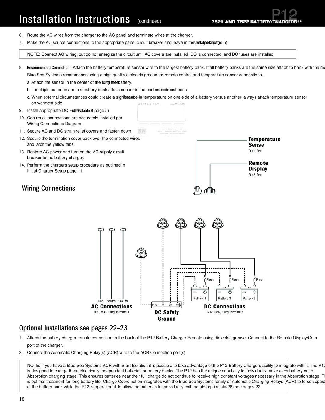
Wiring Connections
Temperature Sense
RJ11 Port
Remote
Display
RJ45 Port
Line | Neutral | Ground |
AC Connections
#8 (M4) Ring Terminals | DC Safety |
| Ground |
Optional Installations see pages 22–23
![]() Fuse
Fuse ![]() Fuse
Fuse ![]() Fuse
Fuse
Battery 1 |
| Battery 2 |
| Battery 3 |
|
|
|
|
|
DC Connections
1/4" (M6) Ring Terminals
1.Attach the battery charger remote connection to the back of the P12 Battery Charger Remote using dielectric grease. Connect to the Remote Display/Com port of the charger.
2.Connect the Automatic Charging Relay(s) (ACR) wire to the ACR Connection port(s)
NOTE: If you have a Blue Sea Systems ACR with Start Isolation it is possible to take advantage of the P12 Battery Chargers ability to integrate with it. The P12 is designed to charge three electrically independent batteries or battery banks. The P12 has the unique capability to individually move each battery out of Absorption charging stage. This ensures batteries near their full charge do not continue to receive high constant voltages necessary in the Absorption stage. This is optimal treatment for long battery life. Charge Coordination integrates with the Blue Sea Systems family of Automatic Charging Relays (ACR) to force separation of the battery bank while the P12 is operational, to allow the batteries to individually exit the absorption stage. (see pages
10Specifications are subject to change. See bluesea.com/P12 for current information.