Installation Instructions | P12 |
7521 AND 7522 BATTERY CHARGERS |
The P12 Battery Charger default startup mode is “User”. The battery charger will maintain a voltage but will not charge batteries in this mode. After proper installation see page 11 to set up your battery type.
Installation Steps
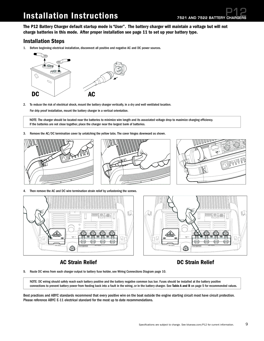
1. Before beginning electrical installation, disconnect all positive and negative AC and DC power sources.
DC
AC
2.To reduce the risk of electrical shock, mount the battery charger vertically, in a dry and well ventilated location. For drip proof installation, mount the battery charger in a vertical orientation.
NOTE: The charger should be located near the batteries to minimize wire length and its associated voltage drop to maximize charging efficiency. If the batteries are not close together, place the charger near the largest bank of batteries.
3. Remove the AC/DC termination cover by unlatching the yellow tabs. The cover hinges downward as shown.
4.Then remove the AC and DC wire termination strain relief by unfastening the screws.
AC Strain Relief | DC Strain Relief |
5.Route DC wires from each charger output to battery fuse holder, see Wiring Connections Diagram page 10.
NOTE: DC wiring should safely reach each battery positive and the battery negative common bus bar. Fuses should be installed at the battery positive connections to prevent battery power from feeding back into a fault in the wiring, or in the battery charger. See Table A and B on page 5 for recommended values.
Best practices and ABYC standards recommend that every positive wire on the boat outside the engine starting circuit most have circuit protection. Please reference ABYC
Specifications are subject to change. See bluesea.com/P12 for current information. | 9 |