Model AX-2320
Model AX-2330
Congratulations
Important Safety Instructions
Wet For home use only
Call 1-877-263-9500 to arrange for service
Washable Shaver
Use only in dry condition Do not submerge shaver into water
Precautions on Using the Shaver
Headguard trimmer
Cleaning brush
Inner cutters
Normal replacement period for the 3 floating heads
Keep the unit clean and dry all times
Feeling for your shaver
Shaving Tips
Cleaning Your Shaver
Trimmer in its off position when not in use
Parts section of this manual
To Shave Longer Hairs, Sideburns Or Beards
Assembly back into place
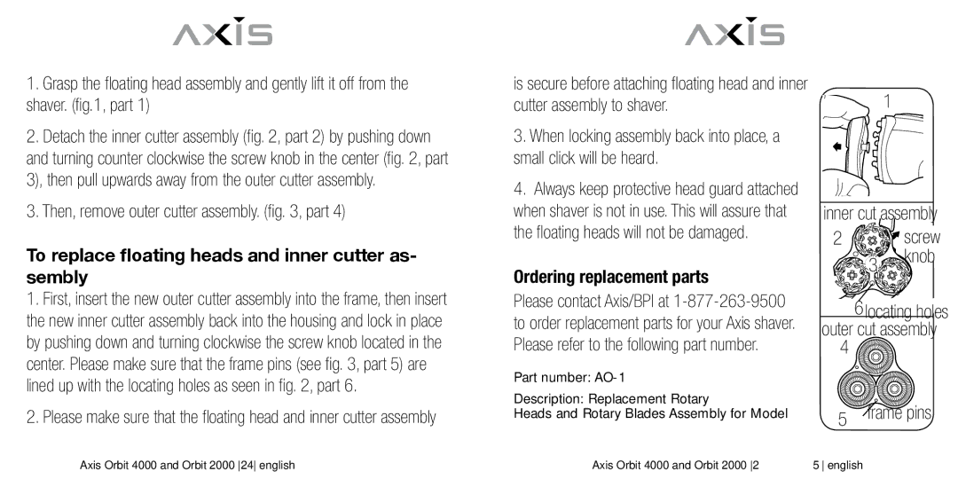
Mount. fig Remove inner cutter assembly
Trimmer Cleaning
Remove loose hairs on cutter
Operating Voltage
Charging Indicator Green Models AX-2320, AX-2330
Worldwide VoltageAX-2330
Storing the Shaver and Power Cord
Remove the back cover to expose the batteries. fig
To remove floating heads and inner cutter assembly
Ordering replacement parts
Then, remove outer cutter assembly. , part
To replace floating heads and inner cutter as- sembly
Year Limited Warranty
If your shaver requires service
Limitations and Exclusions
There are no express warranties except as listed above
Made in China
Pour limiter les risques d’électrocution
Instructions Importantes Concernant Votre Sécurité
NE PAS Utiliser le rasoir dans le bain ou sous la douche
Avertissement
Rasoir Lavable
Conservez CES Instructions
Age 19. N’utilisez pas le rasoir jusqu’à ce qu’il ait séché
Précautions D’EMPLOI DU Rasoir
LES Pièces DE Votre Rasoir
Conseils Pour LE Rasage
’adapter à l’utilisation du rasoir
Maintenez l’appareil propre et sec à tout moment
Comment tailler les favoris, les moustaches ou les barbes
Résultats optimaux
Sa position verrouillée figure
Poussez le bouton du taille-favoris en haut dans
Retirez l’ensemble des têtes
Supérieur de votre moustache
Soulevant vers le haut. fig
Flottantes du boîtier du rasoir en le
Tension de fonctionnement
Nettoyage de la tondeuse
Tension adaptable dans le monde entier AX
Tout d’abord, connectez le cor
Charger le rasoir AX-2320/AX-2330
Témoin de charge Vert des modèles AX-2320, AX-2330
Et/ou de blessures suite à des
Comment enlever les batteries/piles pour les jeter/recycler
Rasoir. fig
Veillez à effectuer cette opération
Détachez les couteaux internes , partie 2 en poussant vers
Sur le rasoir
Dans la , partie
Au centre
Trous de positionnement Ensemble des couteaux externes
Garantie Limitée DE 1 AN
Service de réparation
Limites ET Exclusions
Fabrique en Chine
Peligro
Instrucciones Importantes Para SU Seguridad
No USE la afeitadora mientras se baña o ducha
Advertencia
Máquina DE Afeitar Lavable
Conserve Estas Instrucciones
Precauciones AL Usar LA Afeitadora
No utilice la máquina de afeitar hasta que se ha secado
Page
Cabezaes flotantes Cuchillas interiores
Protector de la cabeza
LED indicadora de carga
Cepillo para limpieza
Consejos para afeitarse
Acostumbrarse a la afeitadora
Mantenga la unidad limpia y seca en todo momento
Período de uso inicial, y desaparecerá con el uso normal
De seguro
Para cortar patillas, bigotes o barbas
La parte superior del bigote
Para la parte superior del bigote. Figura
Limpieza de su afeitadora
Voltajes
Limpieza del recortador
Voltaje universal AX-2330
Desde que están totalmente
Recargar la afeitadora AX-2320/AX-2330
Madamente 2 semanas de afeitadas
De cualquier tomacorriente
Cómo sacar las baterías para desecharlas o reciclarlas
Quitar la cubierta posterior para exponer las baterías. fig
Perilla del tornillo
Montaje interno el cortador
Luego, quite el conjunto de la cuchilla exterior. , parte
Pedido de partes de repuesto
Garantía Limitada POR UN AÑO
Si su afeitadora necesita servicio
Limitaciones Y Exclusiones
Comuníquese con la línea gratuita de Axis/BPI
Fabricado en China
Page
Glendale Heights, Illinois 60139 USA Made in China

![]()
