5Speaker Assembly Angle Adjustment and Locking Procedure
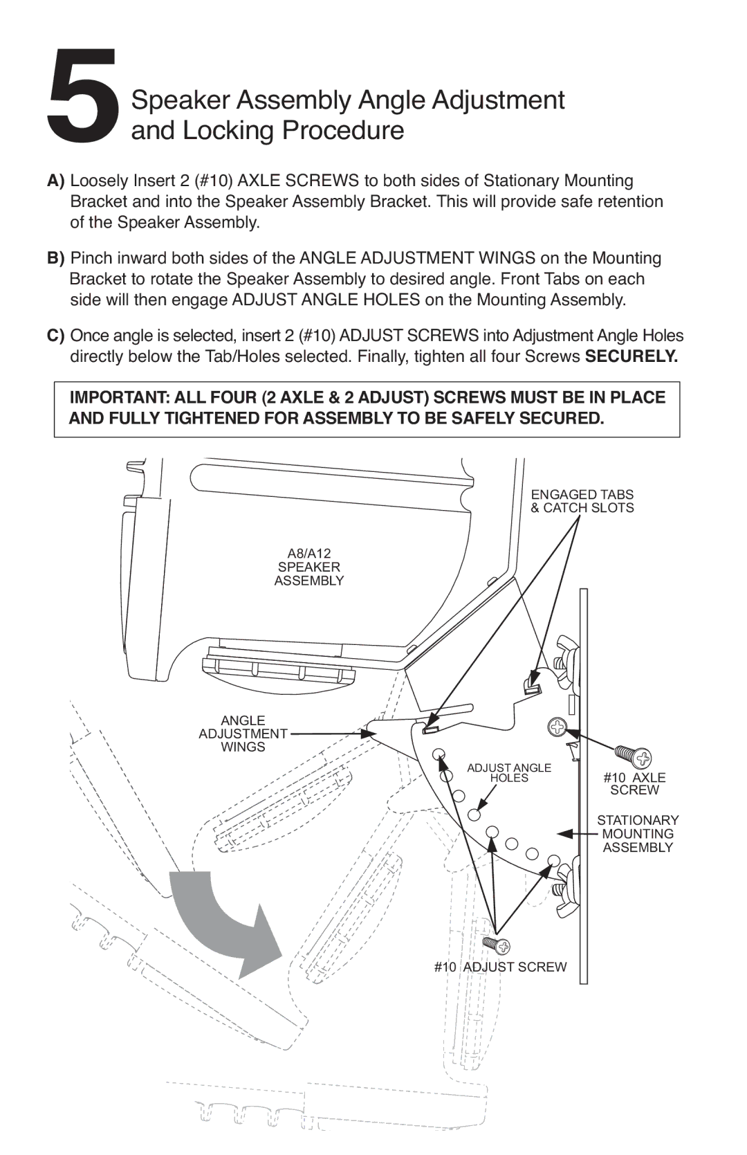
A)Loosely Insert 2 (#10) AXLE SCREWS to both sides of Stationary Mounting Bracket and into the Speaker Assembly Bracket. This will provide safe retention of the Speaker Assembly.
B)Pinch inward both sides of the ANGLE ADJUSTMENT WINGS on the Mounting Bracket to rotate the Speaker Assembly to desired angle. Front Tabs on each side will then engage ADJUST ANGLE HOLES on the Mounting Assembly.
C)Once angle is selected, insert 2 (#10) ADJUST SCREWS into Adjustment Angle Holes directly below the Tab/Holes selected. Finally, tighten all four Screws SECURELY.
IMPORTANT: ALL FOUR (2 AXLE & 2 ADJUST) SCREWS MUST BE IN PLACE AND FULLY TIGHTENED FOR ASSEMBLY TO BE SAFELY SECURED.
ENGAGED TABS & CATCH SLOTS
A8/A12
SPEAKER
ASSEMBLY
ANGLE
ADJUSTMENT ![]()
![]()
WINGS
ADJUST ANGLE
HOLES#10 AXLE
SCREW
STATIONARY
![]()
![]() MOUNTING
MOUNTING
ASSEMBLY
#10 ADJUST SCREW
