Manuals
/
Bosch Appliances
/
Household Appliance
/
Water Heater
Bosch Appliances
250SX LP, 250SX NG
manual
SX Functional scheme
Models:
250SX NG
250SX LP
1
28
36
36
Download
36 pages
43.85 Kb
25
26
27
28
29
30
31
32
Troubleshooting
Install
Parts list
Flow/temperature charts
Warranty
Dimension
Reset button
Adjusting the unit
Temperature selection
Safety
Page 28
Image 28
250 SX Functional scheme
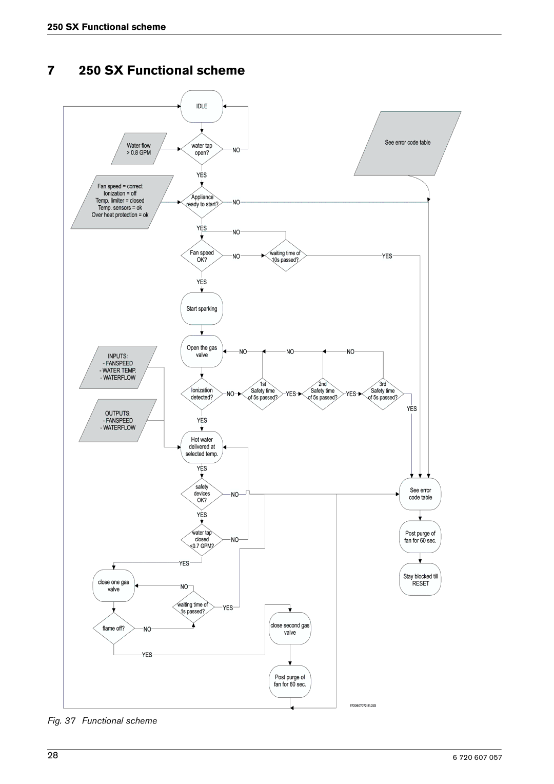
7
250 SX Functional scheme
Fig. 37 Functional scheme
28
6 720 607 057
Page 27
Page 29
Page 28
Image 28
Page 27
Page 29
Contents
SX NG SX LP
What to do if you smell gas
For your safety
Index
Index
Featuring
FCC
250 SX Specifications Technical data
Features
Appliance details
Dimensions
Safety devices
Combustion
Gas types
Dimensions and Minimum installation clearances
Dimensions
General rules to follow for safe operation
Proper location for installing your heater
Venting
Clearances
Mounting installation
Combustion air requirements
Venting
Room
Minimum exhaust vent size and length
Venting options
Appliance details Room sealed installation Twin Pipe System
Open combustion installation Single Pipe System
Description Minimum distance
720 607
Shown
GAS Line Sizing
For Natural GAS
For LP GAS
Gas line sizing
Be Included in the Pipe Sizing
Water connections
Plumbing Connections and Pressure Relief Valve
For your safety read before operating your water heater
Electrical connections
Operating instructions
What to do if YOU Smell GAS
To Turn OFF GAS to Appliance
Power
Temperature selection
Operation instructions
Operation instructions
Operation instructions Setting the water temperature
Flow/temperature charts
Use of remote control accessory
Reset button
Operation
Program button
Maintenance and service
Troubleshooting
Temperature balance valves
Troubleshooting
Unbalanced pressure in water lines
Troubleshooting Display Cause Solution
Chapter
Electrical diagram
Electrical diagram
SX Functional scheme
SX Functional scheme
Interior components diagram and parts list
Interior components diagram and parts list
Interior components
Components diagram
Components Diagram
Parts list
Description Reference
Special adjustment for measuring and adjusting CO2 levels
Adjusting the unit
Adjusting
Leave Program mode
Protecting the environment
Protecting the environment
Packing
Components
Twelve Year Limited Warranty
Controlled Energy Corp
Top
Page
Image
Contents