Special adjustment for measuring and adjusting CO2 levels
9Special adjustment for measuring and adjusting CO2 levels
The CO2 can only be adjusted by a certified gas technician with a calibrated CO2 analyzer.
Caution: Converting the gas type can only be done by a certified gas technician with a calibrated CO2 analyzer. Call CEC for conversion instructions.
Caution: Adjustments must only be carried out by authorized service personnel only.
Caution: The appliance should always be disconnected from the power supply before any maintenance is carried out.
9.1Adjusting the unit
Factory settings of this appliance are listed in table 7. Further adjustment is only needed if optimal CO2 level is required in order to assure the minimum possible CO2 emissions. In this case a CO2 analyzer is required.
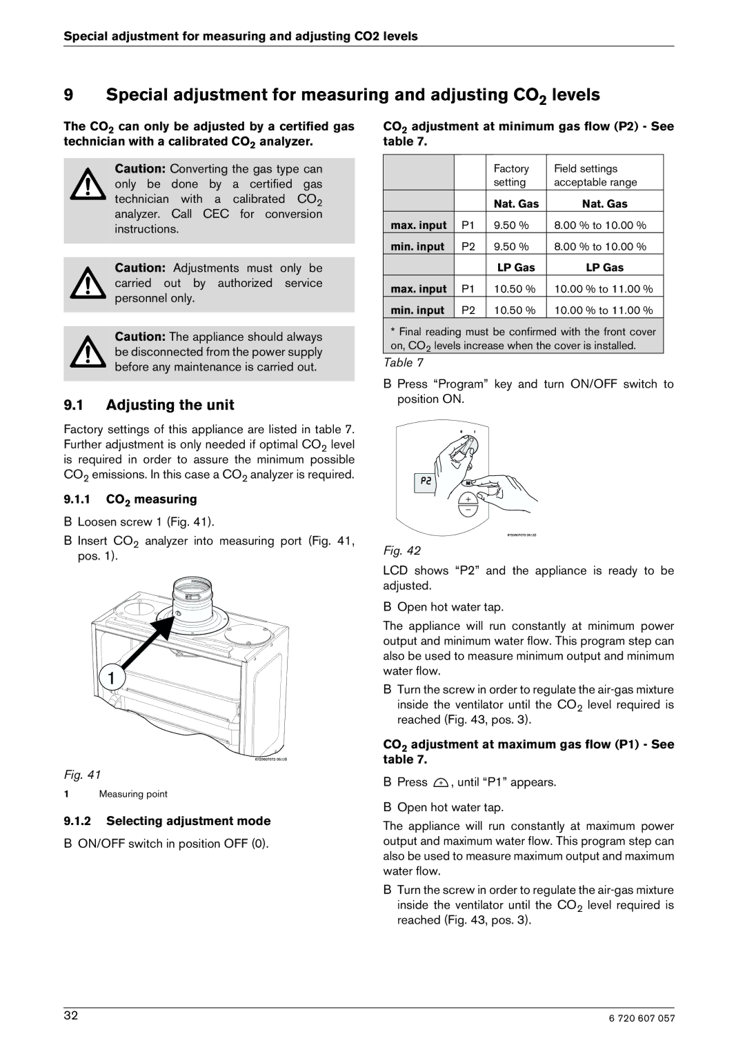
9.1.1CO2 measuring
BLoosen screw 1 (Fig. 41).
B Insert CO2 analyzer into measuring port (Fig. 41, pos. 1).
Fig. 41
1Measuring point
9.1.2Selecting adjustment mode
BON/OFF switch in position OFF (0).
CO2 adjustment at minimum gas flow (P2) - See table 7.
|
| Factory | Field settings |
|
| setting | acceptable range |
|
| Nat. Gas | Nat. Gas |
max. input | P1 | 9.50 % | 8.00 % to 10.00 % |
min. input | P2 | 9.50 % | 8.00 % to 10.00 % |
|
| LP Gas | LP Gas |
max. input | P1 | 10.50 % | 10.00 % to 11.00 % |
min. input | P2 | 10.50 % | 10.00 % to 11.00 % |
* Final reading must be confirmed with the front cover on, CO2 levels increase when the cover is installed.
Table 7
B Press “Program” key and turn ON/OFF switch to position ON.
Fig. 42
LCD shows “P2” and the appliance is ready to be adjusted.
BOpen hot water tap.
The appliance will run constantly at minimum power output and minimum water flow. This program step can also be used to measure minimum output and minimum water flow.
BTurn the screw in order to regulate the
inside the ventilator until the CO2 level required is reached (Fig. 43, pos. 3).
CO2 adjustment at maximum gas flow (P1) - See table 7.
BPress ![]() , until “P1” appears.
, until “P1” appears.
BOpen hot water tap.
The appliance will run constantly at maximum power output and maximum water flow. This program step can also be used to measure maximum output and maximum water flow.
BTurn the screw in order to regulate the
inside the ventilator until the CO2 level required is reached (Fig. 43, pos. 3).
32 | 6 720 607 057 |