Troubleshooting
Display | Cause | Solution | |
|
|
| |
E9 | Temperature limiter opened circuit (overheat). | Check connections.* | |
| Trips at 220F (104C). | Check heat exchanger condition.* | |
|
|
| |
EA | No ionization during safety time (safety time out). | Check gas pressure.* | |
| Note: appliance makes 3 ignition attempts | Check that gas is not diluted with air, as a result | |
| before entering error mode “EA”. | from recent gas pipeline rework.*. | |
|
| Check if vent terminal is blocked (especially when | |
|
| the appliance starts up for some seconds and then | |
EC | The ionization signal momentarily disappeared | ||
looses ionization signal).* | |||
| more then 5 times in less then 30 seconds. | Check ionization electrode.* | |
|
| Check for a proper ground.* | |
|
|
| |
FA | Leakage error (gas valves do not close gas | Check gas valve and control unit.* | |
| circuit). |
| |
|
|
| |
F7 | Ionization error (flame sensing at | Check control unit.* | |
|
|
| |
E0 | Internal software/hardware failure. | Check control unit.* | |
|
|
| |
A7 | Hot water temperature sensor/receiver defect | Check water temperature sensor/receiver and | |
| (from control unit). | connections.* | |
|
| Check room area temperature where heater is | |
|
| located, it must be above 36°F (2°C) | |
|
|
| |
A9 | Hot water temperature sensor/receiver mis- | Close water tap and allow 30 seconds for purging | |
| assembled (from control unit). | time. | |
| Note: if display shows “A9” flashing, the | Open water tap and wait for 2 minutes to see if A9 | |
| appliance can be operated normally, but | message is deleted from the display. | |
| performance may be affected. | Check that the water temperature sensor/receiver is | |
|
| properly assembled in the water pipe.* | |
|
| Check that the water temperature sensor/receiver is | |
|
| in proper condition.* | |
|
|
| |
C1 | FAN rotation too low at | Check supply voltage.* | |
| unit). | Check fan and connections.* | |
|
| Check control unit.* | |
|
| Check if vent terminal is blocked or if vent terminal is | |
|
| according with chapter 2.9. * | |
|
| Check CO2 levels (see chapter 9).* | |
|
|
| |
C6 | FAN rotation too low at operation (from control | Check supply voltage.* | |
| unit). | Check fan and connections.* | |
|
| Check control unit.* | |
|
| Check if vent terminal is according with | |
|
| chapter 2.9.* | |
|
|
| |
C7 | No rotational speed sensor signal from FAN | Check fan and connections.* | |
|
| Check control unit.* | |
|
| Check CO2 levels (see chapter 9).* | |
CA | Water flow signal over specified maximum value | Check water valve and flow sensor.* | |
|
|
| |
E2 | Inlet temperature sensor fault | Check water temperature sensor/receiver and | |
|
| connections.* | |
|
| Check room area temperature where heater is | |
|
| located, it must be above 36°F (2°C) | |
|
|
| |
A2 | Overheat protection fault | Check connections to the overheat protection.* | |
|
| Check sensor continuity.* | |
|
| Check heat exchanger sealings and walls.* | |
|
|
|
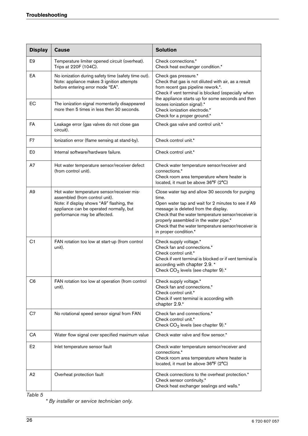
Table 5
* By installer or service technician only.
26 | 6 720 607 057 |
