Interior components diagram and parts list
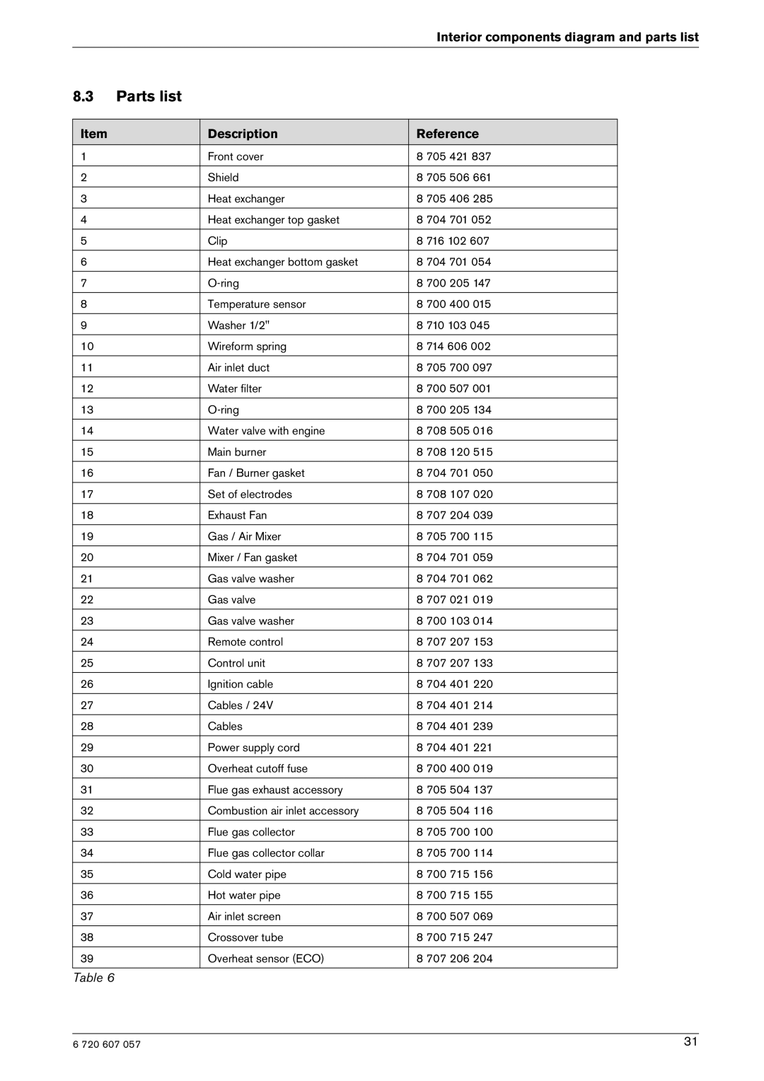
8.3Parts list
Item | Description | Reference |
1 | Front cover | 8 705 421 837 |
|
|
|
2 | Shield | 8 705 506 661 |
|
|
|
3 | Heat exchanger | 8 705 406 285 |
|
|
|
4 | Heat exchanger top gasket | 8 704 701 052 |
|
|
|
5 | Clip | 8 716 102 607 |
|
|
|
6 | Heat exchanger bottom gasket | 8 704 701 054 |
|
|
|
7 | 8 700 205 147 | |
|
|
|
8 | Temperature sensor | 8 700 400 015 |
|
|
|
9 | Washer 1/2" | 8 710 103 045 |
|
|
|
10 | Wireform spring | 8 714 606 002 |
|
|
|
11 | Air inlet duct | 8 705 700 097 |
|
|
|
12 | Water filter | 8 700 507 001 |
|
|
|
13 | 8 700 205 134 | |
|
|
|
14 | Water valve with engine | 8 708 505 016 |
|
|
|
15 | Main burner | 8 708 120 515 |
|
|
|
16 | Fan / Burner gasket | 8 704 701 050 |
|
|
|
17 | Set of electrodes | 8 708 107 020 |
|
|
|
18 | Exhaust Fan | 8 707 204 039 |
|
|
|
19 | Gas / Air Mixer | 8 705 700 115 |
|
|
|
20 | Mixer / Fan gasket | 8 704 701 059 |
|
|
|
21 | Gas valve washer | 8 704 701 062 |
|
|
|
22 | Gas valve | 8 707 021 019 |
|
|
|
23 | Gas valve washer | 8 700 103 014 |
|
|
|
24 | Remote control | 8 707 207 153 |
|
|
|
25 | Control unit | 8 707 207 133 |
|
|
|
26 | Ignition cable | 8 704 401 220 |
|
|
|
27 | Cables / 24V | 8 704 401 214 |
|
|
|
28 | Cables | 8 704 401 239 |
|
|
|
29 | Power supply cord | 8 704 401 221 |
|
|
|
30 | Overheat cutoff fuse | 8 700 400 019 |
|
|
|
31 | Flue gas exhaust accessory | 8 705 504 137 |
|
|
|
32 | Combustion air inlet accessory | 8 705 504 116 |
|
|
|
33 | Flue gas collector | 8 705 700 100 |
|
|
|
34 | Flue gas collector collar | 8 705 700 114 |
|
|
|
35 | Cold water pipe | 8 700 715 156 |
|
|
|
36 | Hot water pipe | 8 700 715 155 |
|
|
|
37 | Air inlet screen | 8 700 507 069 |
|
|
|
38 | Crossover tube | 8 700 715 247 |
|
|
|
39 | Overheat sensor (ECO) | 8 707 206 204 |
|
|
|
Table 6
6 720 607 057 | 31 |
