SECTION 2: INSTALLING THE DVR1
BOSCH
BOSCH
BOSCH
|
| CONSOLE |
|
|
|
|
|
|
|
|
|
|
|
| SVHS IN | VCR | VCR | MON B MON A | 1 | 2 |
|
|
|
|
| 9 | 10 |
KEYBD |
| IN | OUT | 3 | 4 | 5 | 6 | 7 | 8 |
| |||
| SVHS OUT | SDA |
| ALARM |
|
|
|
|
|
|
|
|
|
Multiplexer
ACCESSORIES
|
| 1 | 5 |
ETHERNET | 1 ALARM IN |
|
|
2 ALARM OUT |
|
| |
10/100 | 3 RECORD START IN | 6 | 9 |
| 4 ALARM RECORD RESET |
| 12VDC |
| 5 VEXT PULSE OUT |
|
6 ERROR OUT
7 GROUND
8 VIDEOLOSS OUT
9 DISK END OUT
DVR1
KeyboardEthernet
| BOSCH |
|
|
|
|
11 | 12 | 13 | 14 | 15 | 16 |
| RS- 232 |
| AUDIO IN | VIDEO IN | |
| SCSI |
|
|
|
|
|
|
| AUDIO OUT | ||
|
|
|
|
| SCSI |
|
|
|
| Network | |
BOSCH
Audio
(Optional)
Microphone
(Optional)
Figure 2A – Sample DVR1 System Installation
Figure 2A provides an illustration of a typical DVR1 system installation. Consider the peripheral devices necessary for your system application, and perform the system connections according to the following installation instructions.
2.1Mounting
The DVR1 is supplied as a desktop unit. If desired, your unit may be rack mounted using the rack mount kit (included with the unit). Ensure that the mounting/installation location provides adequate ventilation and protection from moisture. Do not obstruct the ventilation holes at the sides of the unit.
2.2Connecting the DVR1
Rear Panel Connections
1. Refer to Figure 2B for details on the input/output connections supplied by the DVR1.
ETHERNET
10/100
1
| 1 | 5 |
1 ALARM IN |
|
|
2 ALARM OUT |
|
|
3 RECORD START IN | 6 | 9 |
4 ALARM RECORD RESET
5 VEXT PULSE OUT
6 ERROR OUT
7 GROUND
8 VIDEOLOSS OUT
9 DISK END OUT
3 | 5 | 6 | 8 | 10 |
ACCESSORIES | AUDIO IN | VIDEO IN | ||
12V DC | SCSI |
|
|
|
|
| AUDIO OUT | VIDEO OUT | |
|
|
| ||
2 | 4 | 7 | 9 | 11 |
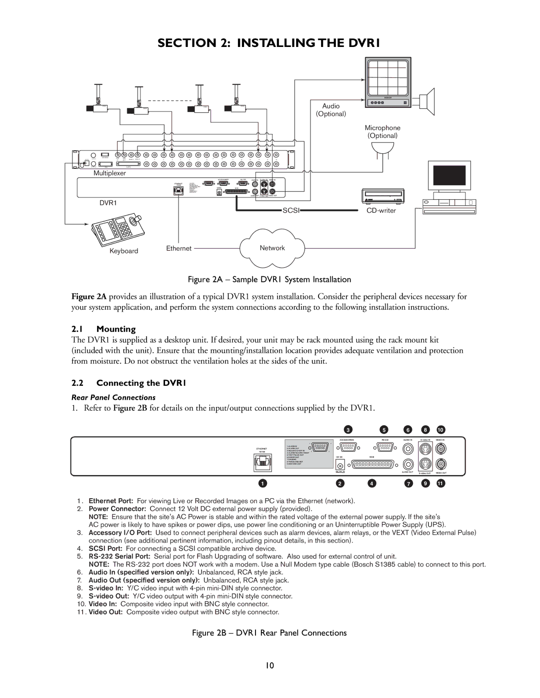
1 . Ethernet Port: For viewing Live or Recorded Images on a PC via the Ethernet (network).
2.Power Connector: Connect 12 Volt DC external power supply (provided).
NOTE: Ensure that the site's AC Power is stable and within the rated voltage of the external power supply. If the site's AC power is likely to have spikes or power dips, use power line conditioning or an Uninterruptible Power Supply (UPS).
3.Accessory I/O Port: Used to connect peripheral devices such as alarm devices, alarm relays, or the VEXT (Video External Pulse) connection (see additional pertinent information, including pinout details, in this section).
4.SCSI Port: For connecting a SCSI compatible archive device.
5.
NOTE: The
6.Audio In (specified version only): Unbalanced, RCA style jack.
7.Audio Out (specified version only): Unbalanced, RCA style jack.
8.
9.
10.Video In: Composite video input with BNC style connector.
11 . Video Out: Composite video output with BNC style connector.
Figure 2B – DVR1 Rear Panel Connections
10