2.Connect all peripherals (e.g. cameras, monitors, etc.) to the corresponding inputs/outputs on the DVR1 rear panel.
CAUTION: DO NOT connect both
3.When all connections have been completed, apply power to the system.
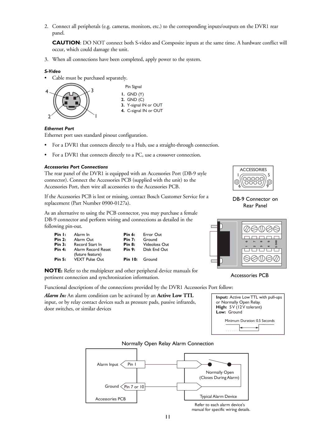
•Cable must be purchased separately.
4
2
Pin Signal
3
1.GND (Y)
2.GND (C)
3.
4.
1
Ethernet Port
Ethernet port uses standard pinout configuration.
•For a DVR1 that connects directly to a Hub, use a
•For a DVR1 that connects directly to a PC, use a crossover connection.
Accessories Port Connections
The rear panel of the DVR1 is equipped with an Accessories Port
ACCESSORIES | |
1 | 5 |
6 | 9 |
If the Accessories PCB is lost or missing, contact Bosch Customer Service for a |
| |
replacement (Part Number | ||
Rear Panel | ||
|
As an alternative to using the PCB connector, you may purchase a female
Pin 1: | Alarm In | Pin 6: | Error Out |
Pin 2: | Alarm Out | Pin 7: | Ground |
Pin 3: | Record Start In | Pin 8: | Videoloss Out |
Pin 4: | Alarm Record Reset | Pin 9: | Disk End Out |
Pin 5: | (future feature) | Pin 10: |
|
VEXT Pulse Out | Ground |
NOTE: Refer to the multiplexer and other peripheral device manuals for pertinent connection and synchronization information.
6 | 7 | 8 | 9 | GND |
1 | 2 | 3 | 4 | 5 |
Accessories PCB
Functional descriptions of the connections provided by the DVR1 Accessories Port follow:
Alarm In: An alarm condition can be activated by an Active Low TTL input, or by relay contact devices such as pressure pads, passive infrareds, door switches, or similar devices
Input: Active Low TTL with
High: 5 V (12 V tolerant)
Low: Ground
Minimum Duration: 0.5 Seconds
Normally Open Relay Alarm Connection
Alarm Input | Pin 1 |
|
Ground | Pin 7 or 10 | |
Accessories PCB | ||
|
|
|
Normally Open
(Closes During Alarm)
Typical Alarm Device
Refer to each alarm device's manual for specific wiring details.
11