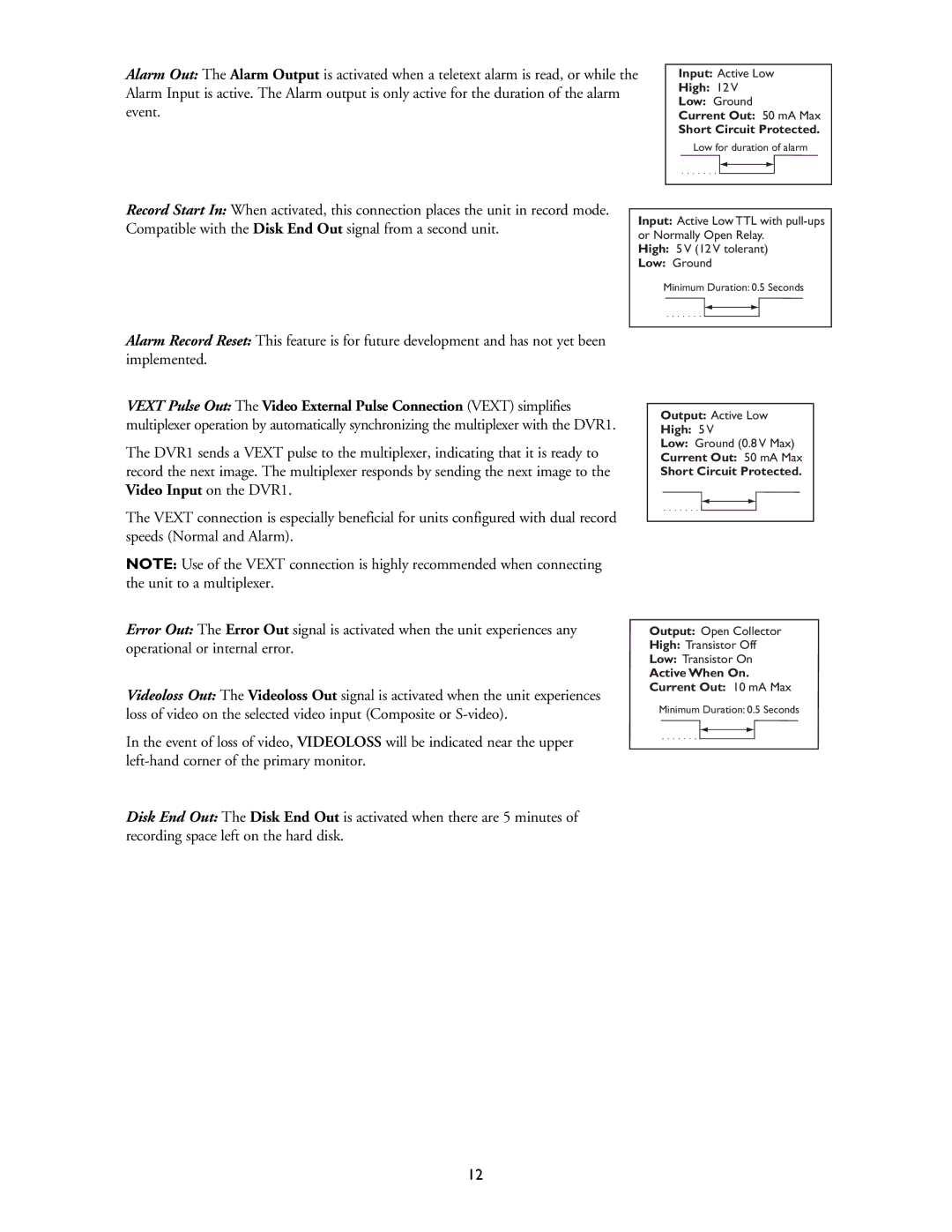
Alarm Out: The Alarm Output is activated when a teletext alarm is read, or while the Alarm Input is active. The Alarm output is only active for the duration of the alarm event.
Input: Active Low
High: 12 V
Low: Ground
Current Out: 50 mA Max
Short Circuit Protected.
Low for duration of alarm
Record Start In: When activated, this connection places the unit in record mode. Compatible with the Disk End Out signal from a second unit.
Input: Active Low TTL with
High: 5 V (12 V tolerant)
Low: Ground
Minimum Duration: 0.5 Seconds
Alarm Record Reset: This feature is for future development and has not yet been implemented.
VEXT Pulse Out: The Video External Pulse Connection (VEXT) simplifies multiplexer operation by automatically synchronizing the multiplexer with the DVR1.
The DVR1 sends a VEXT pulse to the multiplexer, indicating that it is ready to record the next image. The multiplexer responds by sending the next image to the Video Input on the DVR1.
The VEXT connection is especially beneficial for units configured with dual record speeds (Normal and Alarm).
NOTE: Use of the VEXT connection is highly recommended when connecting the unit to a multiplexer.
Error Out: The Error Out signal is activated when the unit experiences any operational or internal error.
Videoloss Out: The Videoloss Out signal is activated when the unit experiences loss of video on the selected video input (Composite or
In the event of loss of video, VIDEOLOSS will be indicated near the upper
Disk End Out: The Disk End Out is activated when there are 5 minutes of recording space left on the hard disk.
Output: Active Low
High: 5 V
Low: Ground (0.8 V Max)
Current Out: 50 mA Max
Short Circuit Protected.
Output: Open Collector
High: Transistor Off
Low: Transistor On
Active When On. Current Out: 10 mA Max
Minimum Duration: 0.5 Seconds
12
