14 en Install the Bases | F220 Series Detectors with |
|
|
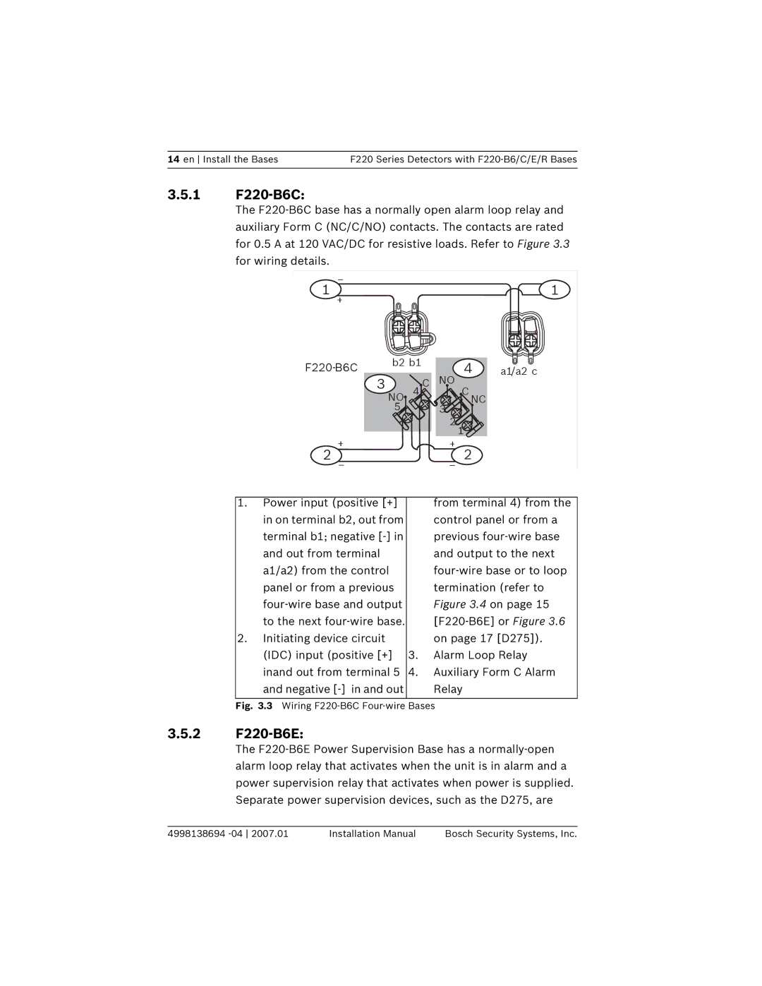
3.5.1F220-B6C:
The
_ |
|
|
|
|
|
|
1 + |
|
|
|
|
| 1 |
| b2 b1 |
|
| 4 | a1/a2 c | |
3 |
| C | NO | |||
| 4 | C NC |
| |||
| NO |
| 3 |
| ||
| 5 |
|
|
|
| |
|
|
|
| 2 1 |
| |
2 + |
|
|
| + | 2 |
|
1. Power input (positive [+] |
| from terminal 4) from the |
in on terminal b2, out from |
| control panel or from a |
terminal b1; negative |
| previous |
and out from terminal |
| and output to the next |
a1/a2) from the control |
| |
panel or from a previous |
| termination (refer to |
| Figure 3.4 on page 15 | |
to the next |
| |
2. Initiating device circuit |
| on page 17 [D275]). |
(IDC) input (positive [+] | 3. | Alarm Loop Relay |
inand out from terminal 5 | 4. | Auxiliary Form C Alarm |
and negative |
| Relay |
|
|
|
Fig. 3.3 Wiring F220-B6C Four-wire Bases
3.5.2F220-B6E:
The
4998138694 | Installation Manual | Bosch Security Systems, Inc. |