F220 Series Detectors with | Install the Bases en 15 |
|
|
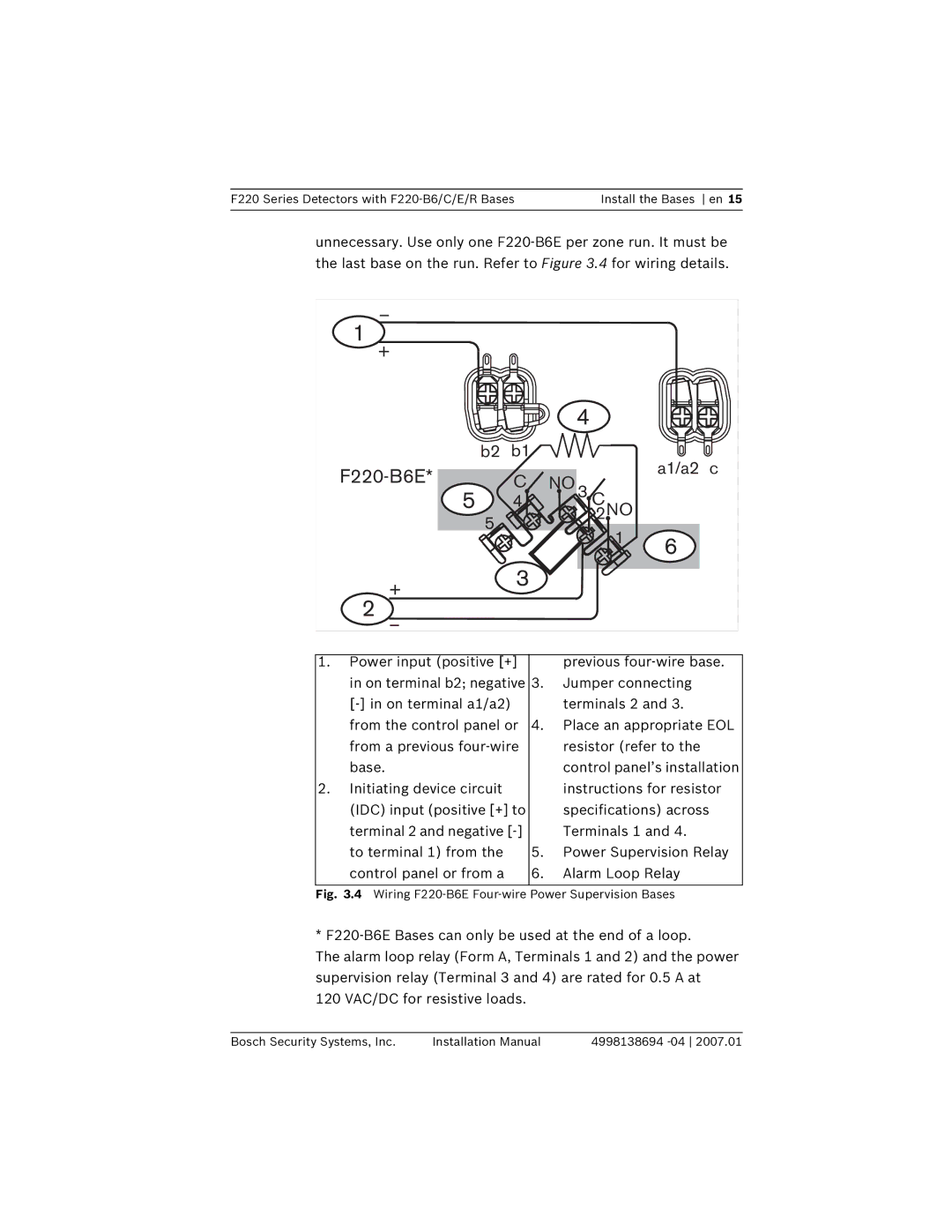
unnecessary. Use only one
| _ |
|
|
|
|
|
1 | + |
|
|
|
|
|
|
|
|
|
|
| |
|
|
|
| 4 |
|
|
| b2 | b1 |
|
| a1/a2 | c |
| C | NO |
| |||
3 C |
|
| ||||
| 5 | 4 |
|
|
| |
| 5 |
|
| 2NO |
|
|
|
|
| 1 | 6 |
| |
|
|
|
|
| ||
|
|
|
|
|
| |
| + | 3 |
|
|
|
|
2 |
|
|
|
|
| |
_ |
|
|
|
|
| |
1. Power input (positive [+] |
| previous |
in on terminal b2; negative | 3. | Jumper connecting |
| terminals 2 and 3. | |
from the control panel or | 4. | Place an appropriate EOL |
from a previous |
| resistor (refer to the |
base. |
| control panel’s installation |
2. Initiating device circuit |
| instructions for resistor |
(IDC) input (positive [+] to |
| specifications) across |
terminal 2 and negative |
| Terminals 1 and 4. |
to terminal 1) from the | 5. | Power Supervision Relay |
control panel or from a | 6. | Alarm Loop Relay |
|
|
|
Fig. 3.4 Wiring F220-B6E Four-wire Power Supervision Bases
*
The alarm loop relay (Form A, Terminals 1 and 2) and the power supervision relay (Terminal 3 and 4) are rated for 0.5 A at 120 VAC/DC for resistive loads.
Bosch Security Systems, Inc. | Installation Manual | 4998138694 |