Bosch Appliances F220-B6 installation manual Wire the Bases, Terminal Connections, EOL Resistors

Models: F220-B6

1 28
Download 28 pages 11.75 Kb
Page 11
Image 11

F220 Series Detectors with F220-B6/C/E/R Bases

Install the Bases en 11


3.2Wire the Bases

CAUTION! When wiring bases, all terminal screws

!including those not wired must be tightened to prevent loose screw heads from making intermitent electrical

contact with the detector head.

3.2.1Terminal Connections

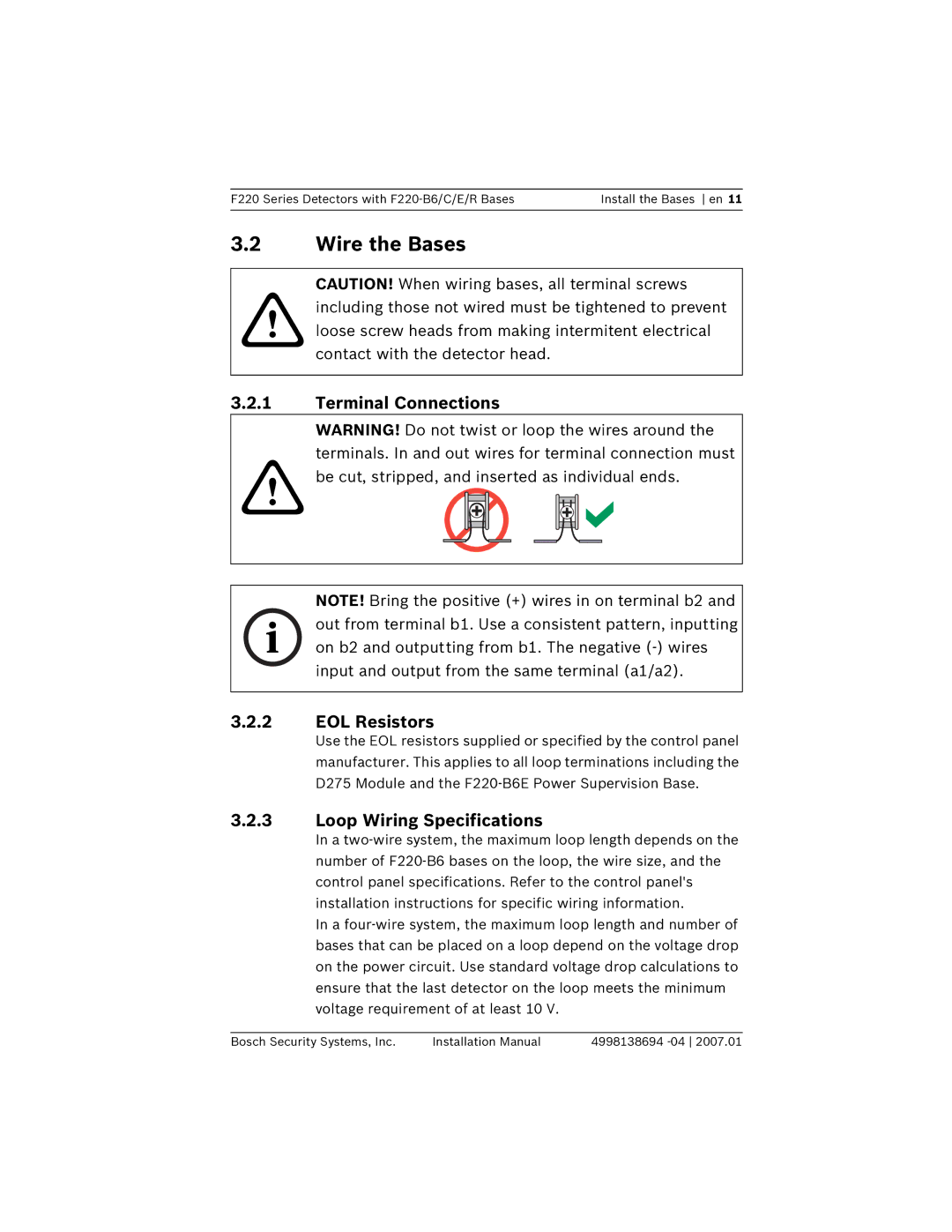
WARNING! Do not twist or loop the wires around the terminals. In and out wires for terminal connection must

!be cut, stripped, and inserted as individual ends.

NOTE! Bring the positive (+) wires in on terminal b2 and

i out from terminal b1. Use a consistent pattern, inputting on b2 and outputting from b1. The negative (-) wires input and output from the same terminal (a1/a2).

3.2.2EOL Resistors

Use the EOL resistors supplied or specified by the control panel manufacturer. This applies to all loop terminations including the D275 Module and the F220-B6E Power Supervision Base.

3.2.3Loop Wiring Specifications

In a two-wire system, the maximum loop length depends on the number of F220-B6 bases on the loop, the wire size, and the control panel specifications. Refer to the control panel's installation instructions for specific wiring information.

In a four-wire system, the maximum loop length and number of bases that can be placed on a loop depend on the voltage drop on the power circuit. Use standard voltage drop calculations to ensure that the last detector on the loop meets the minimum voltage requirement of at least 10 V.

Bosch Security Systems, Inc.

Installation Manual

4998138694 -04 2007.01

Page 11
Image 11
Bosch Appliances F220-B6 Wire the Bases, Terminal Connections, EOL Resistors, Loop Wiring Specifications