Networking CardsPlanning en 9
3 | Planning |
3.1 | General considerations |
If the panel is to be used in a networked system, be careful to plan properly before installing any panels. Check:
–whether the networked panels will be installed near each other or distributed over a wider area
–whether or not any of the networked panels will be in different buildings
–the types and numbers of Networking Cards needed
–interconnection requirements, including the maximum allowable cable lengths which depend on the intended interconnection method (Ethernet, fiber optic cable, or wire).
For each panel, be careful to plan properly before installing any devices. Check:
–the compatibility and number of devices to be connected
–the battery capacity needed
–the wiring requirements, including the maximum allowed cable length
–the installation requirements according to this Installation and Operation Guide,NFPA 72, Local Codes and the Authority Having Jurisdiction (AHJ).
3.2 | Ground Fault Detection |
|
| |||
|
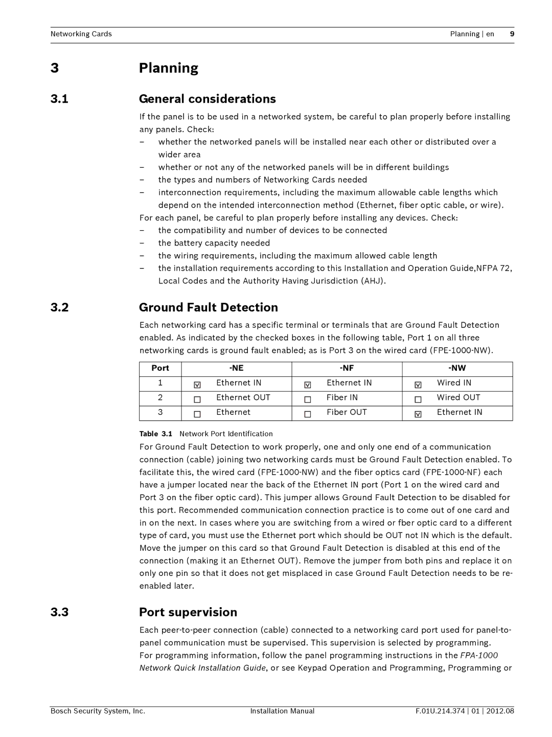
| Each networking card has a specific terminal or terminals that are Ground Fault Detection | ||||
|
| enabled. As indicated by the checked boxes in the following table, Port 1 on all three | ||||
|
| networking cards is ground fault enabled; as is Port 3 on the wired card | ||||
|
|
|
|
|
|
|
|
| Port |
| |||
|
|
|
|
|
|
|
|
| 1 |
| Ethernet IN | Ethernet IN | Wired IN |
|
|
|
|
|
|
|
|
| 2 |
| Ethernet OUT | Fiber IN | Wired OUT |
|
|
|
|
|
|
|
|
| 3 |
| Ethernet | Fiber OUT | Ethernet IN |
|
|
|
|
|
|
|
|
| Table 3.1 | Network Port Identification |
|
| |
|
| For Ground Fault Detection to work properly, one and only one end of a communication | ||||
|
| connection (cable) joining two networking cards must be Ground Fault Detection enabled. To | ||||
|
| facilitate this, the wired card | ||||
|
| have a jumper located near the back of the Ethernet IN port (Port 1 on the wired card and | ||||
|
| Port 3 on the fiber optic card). This jumper allows Ground Fault Detection to be disabled for | ||||
|
| this port. Recommended communication connection practice is to come out of one card and | ||||
|
| in on the next. In cases where you are switching from a wired or fber optic card to a different | ||||
|
| type of card, you must use the Ethernet port which should be OUT not IN which is the default. | ||||
|
| Move the jumper on this card so that Ground Fault Detection is disabled at this end of the | ||||
|
| connection (making it an Ethernet OUT). Remove the jumper from both pins and replace it on | ||||
|
| only one pin so that it does not get misplaced in case Ground Fault Detection needs to be re- | ||||
|
| enabled later. |
|
| ||
3.3 Port supervision
Each
For programming information, follow the panel programming instructions in the
Bosch Security System, Inc. | Installation Manual | F.01U.214.374 01 2012.08 |