Manuals
/
Bosch Appliances
/
Household Appliance
/
Water Heater
Bosch Appliances
GWH-345/450-ESR-N manual Exhaust vent connection, Installation instructions
Models:
GWH-345/450-ESR-L
GWH-345/450-ESR-N
1
15
40
40
Download
40 pages
52.3 Kb
12
13
14
15
16
17
18
19
<
>
Troubleshooting
Specification
Install
Parts list
Electrical diagram
Heater placement and clearances
Warranty
Maintenance
Exhaust vent configuration examples
Connecting manometer
Page 15
Image 15
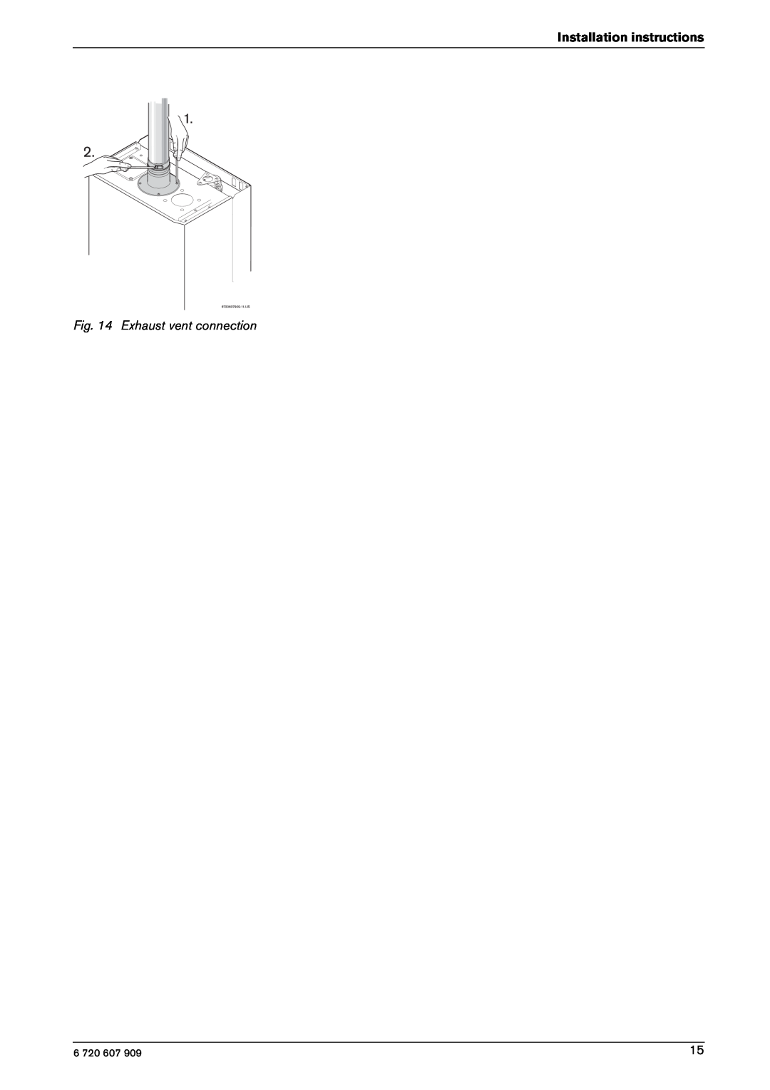
Installation instructions
Fig. 14 Exhaust vent connection
6 720 607 909
15
Page 14
Page 16
Page 15
Image 15
Page 14
Page 16
Contents
GWH 345/450 ESR
Temperature Modulated with Electronic Ignition
Suitable for heating and recirculating potable water
What to do if you smell gas
Index
For your safety
Index
1 Warning
Warning The recirculating water heater must be disconnected from the gas supply piping system during any pressure testing of that system at test pressures equal to or more than 0.5 psig 14” W.C
Dimensions
2.1 Features
2.2 GWH-345/450-ESR Specifications Technical data
Temperature Control
Inlet air restrictors
Fig. 3 Service position to access water and electric connections
2.3 Unpacking the GWH-345/450-ESR heater
Water resistant
Appliance details
2.4 General rules to follow for safe operation
Table 1 Minimum clearances
2.5 Dimensions and minimum installation clearances
Fig. 4 Dimensions
Fig. 5 Minimum clearances
Pump Sizing
Fig. 7 Service position to access water and electric connections
2.6 Applications
Introduction
water flow rate
Table 2 Venting Specifications
pressure
Inlet
3.4 Mounting installation
3 Installation instructions
3.2 Proper location for installing your heater
3.3 Heater placement and clearances
Single pipe
3.5 Combustion air requirements
Fig. 10 Mounting the heater
Twin pipe
Appliances located in confined spaces
Installation instructions
1000 Btu/hr 292.81 watts if all air is taken from inside the building
Vent lengths
3.6.1 Vent material and specifications
Table 3 Venting Specifications
3.6 Venting
Table 4 Vent manufacturer contact information
Vent Safety System
Fig. 13 Maximum vent and combustion air lengths
Vent material
Installation instructions
Fig. 14 Exhaust vent connection
Table 6 Determining equivalent vent length see example in Table
Selecting inlet air restrictor
Exhaust
Intake
Fig. 15 Mounting sequence
Fig. 16 Exhaust air inlet accessory
Table 8 Restrictors table
Combustion air inlet connection
Fig. 18 Horizontal twin pipe termination
Fig. 17 Required condensate drain installation
3.6.4 Room sealed installation Twin pipe
3.6.3 Condensate drain requirements
Fig. 20 Vertical vent termination clearances
3.6.5 Vertical terminations
Horizontal runs
Vent terminations
248 CMR 5.082a1 through
3.6.6.1Requirements for installation in Massachusetts
Attention residents of the Commonwealth of Massachusetts
Installation instructions
Minimum distance
Recommended exhaust vent terminator position
Installation instructions
Description
Fig. 24 Vertical venting installation
3.6.7 Exhaust vent configuration examples
Fig. 22 Horizontal side wall venting installation
Fig. 23 Vertical venting installation - Masonry Chimney
3.7 Gas piping & connections
GAS CONNECTIONS
Installation instructions
Maximum Capacity of Semi-Rigid flexible, non
FOR NATURAL GAS
FOR LP GAS
Installation instructions
Fig. 27 Gas pressure measuring lower tapping
Connecting manometer
3.8 Measuring gas pressure
3.9 Checking restrictor plate size by measuring CO2 level value
Installation instructions
3.10 Water connections
3.11 Electrical connections
Fig. 30 Plumbing Connections and Pressure Relief Valve
4.3 Startup instructions
4.2 For your safety read before operating your water heater
4 Operating instructions
4.1 Initial filling instructions
Fig. 33 Recirculating water temperature adjustment
4.4 Power
4.5 Recirculating water temperature
4.6 Temperature and hot water flow
4.8 Electrical diagram
Fig. 35 Electrical scheme
Operating instructions
Yearly maintenance
5 Maintenance and service
5.1 Service mode
Maintenance and service
Values
Exiting service mode
Mode
Parameter
Possible Cause
Troubleshooting
Troubleshooting
Fault Indication
Check
Troubleshooting
Fault Indication
Possible Cause
7 GWH-345/450-ESR Functional scheme
GWH-345/450-ESR Functional scheme
Functional scheme
Fig. 37 Components
8 Interior components diagram and parts list
Interior components diagram and parts list
8.1 Interior components
8.2 Components diagram
Fig. 38 Components Diagram
Interior components diagram and parts list
Reference
8.3 Parts list
Interior components diagram and parts list
Description
Components
9 Protecting the environment
Protecting the environment
Packing
How to Make a Claim
10 Ten Year Limited Warranty
Ten Year Limited Warranty
Service Labor Costs
BOSCH THERMOTECHNOLOGY CORPORATION
Installer Checklist, to be performed by installer upon installation