Bosch High Performance HD LED Monitors
Page
Table of contents
Troubleshooting Maintenance Technical Specifications
Power Management
Power Consumption LED Indicator
Safety
Important safety instructions
En Safety Bosch High Performance HD LED Monitors
Bosch High Performance Safety en HD LED Monitors
Safety precautions
Important notices
Coax grounding
En Safety Bosch High Performance HD LED Monitors
System ground/Safety ground
Rack-mount
FCC & Ices Information
Informations FCC et Ices
Modèles utilisés aux États-Unis et au Canada uniquement
Disclaimer
Copyright
Trademarks
Customer Support and Service
Mail customer.service@cn.bosch.com
Warranty and more information
Quanti Description
Parts List
Unpacking
Button Description
Access and Connections
Front Control Panel
Rear Panels
UML-273-90
UML-323-90
UML-423-90
UML-553-90
Button/ Description ef Part
LED
Indicates the operating status of the monitor
Menu
Video
Sourc
Enter
Video OUT
Video in Component AC Switch ON/OFF Video in S-VIDEO
Bottom Panel
PIP
Remote Control
Power
Remote Control Battery Installation
Hdmi
DVI2
DVI1
Features
Description
Power
Model No Rated Voltage Power at Rated Sync Range Format
NTSC/PA
VAC
Installing the Monitor
Connecting Power
Connecting the Composite Video Signal to the Monitor
Ventilation
Connecting the Y/C S-Video Signal to the Monitor
Connecting Audio to the Monitor
Connecting the PC Signal to the Monitor
Number Input Ground Signal
DVI Connection
Connecting an Alarm Trigger
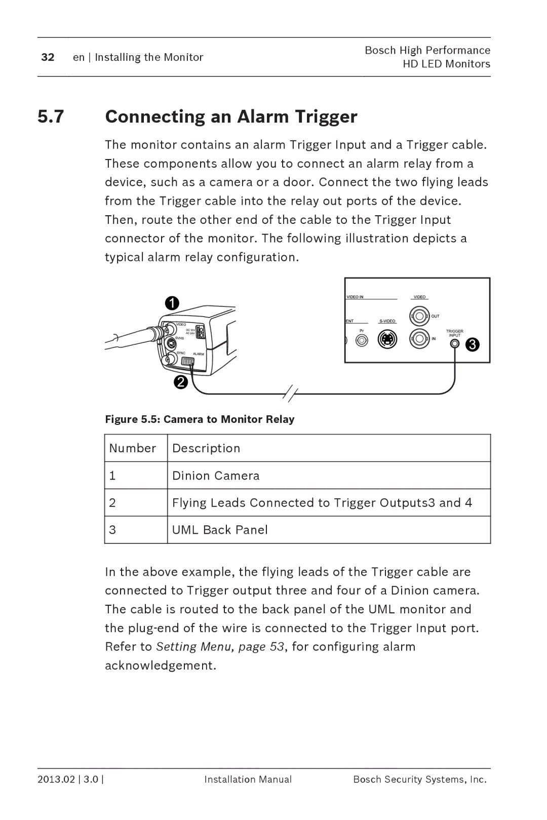
Camera to Monitor Relay
Example Typical Alarm Trigger Configuration
VMD OSD
Trigger Enable Trigger Input
Picture
AV1
Buzzer Trigger Time Trigger Option High Move Enter Exit
DVR
Single / Multiple Monitor Configuration
Description Video Camera Video Out
Accessory Installation
Multiple Monitor Configuration
Placing the Monitor on a Desktop
Application
Mounting the Monitor to a Wall
UML-423-90 UML-553-90
UML-273-90 Location of mounting holes
400 MM
10 UML-423-90 Location of mounting holes
Navigating the Monitor
Navigating the Control Panel
Decreases audio volume Adjusts the value when Scrolls up OSD
Using the Monitor On-screen Display OSD
Menu Selects the on-screen display OSD
Source
Serves as the Enter function for OSD
On-screen Display Menus
Icon Men Function
Picture Menu
DCR OFF
12000K , 9300K, and 6500K
Submenu Definition
DCR
Auto, 1366 x 768, 1360 x 768, 1280 x
Submen Definition
Sound Menu
Sound
Line-Out, and Internal
Option Menu
Options
Aspect Ratio Full
Aspect Ration Selects the Aspect Ratio mode. Choices are
Main Input and Sub Input selects
AV, S-Video, VGA, YPbPr, DVI, and Hdmi
Sub Pictu
Main Picture Input Source
DVI Hdmi
Setting Menu
Setting
Trigger Schedule Display Wall Power Save
Language English Overscan
English, French, Spanish, Dutch, German
Italian, Portuguese, Russian, Polish, Simplified
Chinese and Japanese
On or OFF
Bosch Security Systems, Inc Installation Manual 2013.02
2013.02 Installation Manual Bosch Security Systems, Inc
Bosch Security Systems, Inc Installation Manual 2013.02
Input Source displays the selected input
Operating Time Day & hr displays
Duration the display has been turned on
LED Indicator
Power Management
Power Consumption
Troubleshooting
Problem Solution
Bosch High Performance Troubleshooting en HD LED Monitors
Maintenance
Technical Specifications
Model UML-273-90 UML-323-90 LCD Specifications
PC RGB D-Sub connector
Hdmi DVI-D
Model UML-273-90 UML-323-90
Model UML-423-90 UML-553-90 LCD Specifications
Model UML-423-90 UML-553-90
Page
Bosch Security Systems, Inc