VG4 Modular Camera System
Page
Table of Contents
Keyboard Commands by Number Advanced Features
Using the IP AutoDome
Pelco On-Screen Menus
VG4 Audio Connections
Configuring the IP AutoDome
Troubleshooting Guide 117
Powering On
Getting Started
Establishing AutoDome Control
Seconds and ends with a splash screen
2Keyboard Commands
Basic Keyboard Operation
LCD
Setting the Camera Address
FastAddress
To set an address for a camera without an address
To change or clear an address for a camera with an address
Setting Passwords
Special Passwords
Password Security Level
To set or change a password locked command
Setup Menu
On-Screen Display Menu Navigation
Camera Setup Menu
ATW
Auto
Internal
OFF
Night Mode
Restore
Defaults
60 sec
Lens Setup
Spot
Constant
Fast
PTZ Setup Menu
Normal
Display Setup Menu
Moment
ARY
OSD
Communication Setup Menu
Alarm I/O Setup
Setup
Inputs
Low
Pressure
Outputs Setup Menu
Outputs Setup
Alarm Relay
Outputs
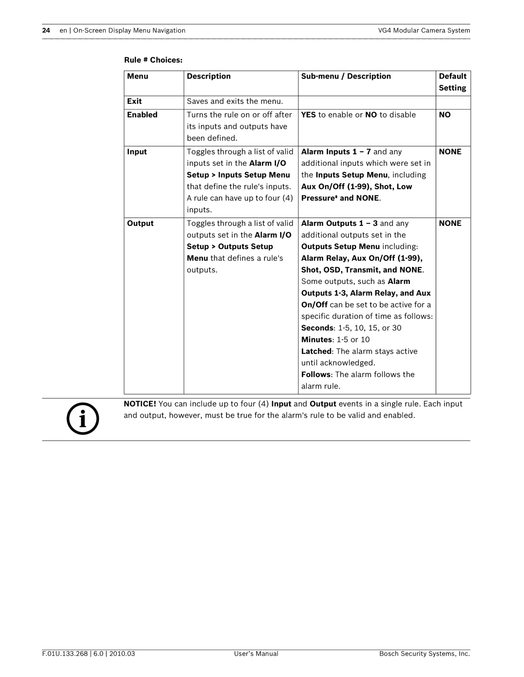
Rule Setup Menu
Rule Setup
Rule
None
Advanced Feature Setup Menu available with Series 500i only
Advanced Feature Setup
Language Menu
Timeout
Timeout Period
Stabilization
AutoTrack
Diagnostics Menu
Alarm Status
Bist
Internal Temp
Security Access
Ctfid Access
Power Up Events
ExtComm Error
11.1 Alarm Status Submenu
Common AutoDome User Commands unlocked
Setting AutoPan Mode
2Setting Preset Shots
4Configuring Preposition Tours
Specifying a Shot or a Sector Title
To start Preposition Tour 1 200, 300, and 500i Series
To stop a Preposition Tour
5Programming the Inactivity Operation
6Recording Tours 300 and 500i Series only
Setting FastAddress with Alternative Protocols
Using an American Dynamics Controller
Alternative Control Protocols
Exit Command Lock
Enter FastAddress
FastAddress
2Using a Pelco Controller
New Fast Address Saved Setup Menu
Setting FastAddress with a Pelco Keyboard
Pelco Protocol Mode
Hardware Configuration
2Pelco Keyboard Commands
Pelco Keyboard Commands
Special Preset Commands
Preset
Pelco On-Screen Menus
Command Lock locked
Pelco menu Bosch menu Setup Menu
Bosch Menu locked
PTZ Setup unlocked
Camera Setup unlocked
Pelco Camera Setup Menu provides access to camera settings
Outdoor
Other Menus
Keyboard Commands by Number
Zone Title menu Enters Zone Title menu. Refer to
Specifying a Shot or a Sector Title,
VG4 Modular Camera System Keyboard Commands by Number en
Advanced Features
Alarm Rules 300 and 500i Series Only
Controlling Alarm Rules
Alarm Rule Examples
Example 2 Advanced Alarm Rule
Example 3 Advanced Alarm Rule using AutoTrack
Click the Online Config button and then expand Alarm
Click Output Option
AutoTrack Operation 500i Series Only
Manual
Automatic
AutoTrack Settings and Recommendations
Setting AutoTrack Optimization Parameters
2AutoTrack Optimization
Dynamic Light Conditions
Consistent Light Conditions
Preset positions 90 through
Virtual Masking 500i Series Only
4Privacy Masking 300 and 500i Series Only
Motion Detection with Region of Interest 500i Series Only
Image Stabilization 500i Series Only
7Pre-position Tour
Using the IP AutoDome
Overview of Features
Connecting the IP AutoDome to the PC
Network switch to bypass the Local Area Network LAN
System Requirements
Below
Configuring the IP AutoDome Camera
AutoDome IP Connection Network Switch Computer
Installing the Required Software
1Changing the Network Settings
Install the software packages using the procedure below
Using the Configuration Manager
Using the IP AutoDome Web Server
Network Settings
6The Livepage
Maximum Number of Connections
Protected IP AutoDome
Protected Network
View Control
Iris open
Digital I/O
Entering a Keyboard Control Command
Triggering Relay
System Log / Event Log
Audio Function
To Enter a Keyboard Control Command
To Set a Preset Shot
Aux Control Tab
Number Description
To View a Preset Shot
Image Resolution
Saving Snapshots
Recording Video Sequences
Audio Line Input Specifications
Wire Specifications
9VG4 Audio Connections
Connections
Click the Transmit Audio radio button to enable for audio
Enabling Audio Transmission
To transmit audio via the IP connection, do the following
5Configuring Gain optional
Configuring the IP AutoDome
10.1 Basic Mode Device Access
Password
Confirm password
10.2 Basic Mode Date/Time
10.3 Basic Mode Network
Dhcp
10.4 Basic Mode Encoder Profile
10.5Basic Mode Audio
DSL
Modem
10.6 Basic Mode Recording
10.7 Basic Mode System Overview
10.8Advanced Mode Identification
Storage medium
10.9Advanced Mode Password
Initiator extension
10.10 Advanced Mode Date/Time
Date format
Device date/Device time
Device time zone
10.11 Advanced Mode Display Stamping
10.12 Advanced Mode Appearance
10.13 Advanced Mode Livepage Functions
10.14 Advanced Mode Logging
10.15 Advanced Mode Picture Settings
10.16 Advanced Mode Encoder Profile
Isdn 2B
Isdn 1B
CIF
10.17 Advanced Mode Encoder Streams
10.18 Advanced Mode Audio
Picture quality
Network
Transmitted, select Off
10.21 Camera Settings Group
10.22 Camera Settings Group
10.23 Advanced Mode Lens 10.24 Lens Settings Group
10.25 Lens Settings Group
10.26 Advanced Mode PTZ 10.27 PTZ Settings Group
10.28 PTZ Settings Group
10.29 Advanced Mode Display 10.30 Display Settings Group
10.31 Display Settings Group
Scene #
Tour
10.32 Display Settings Group
10.33 Advanced Mode Alarm 10.34 Input Options
Custom Tour Period
Custom Tour
10.35 Output Options
Rule Definition
Physical Output
10.36Alarm Rules
Creating Alarm Rules
Basic Alarm Rule Example
Output Option 5 Example
Select Output Option
Click the Type drop-down list and select Transmit
Alarm Rule 1 Example
Advanced Alarm Rule Example using AutoTrack
Audio/BiPhase
10.37Miscellaneous
Address
10.39 Advanced Mode Storage Management
10.38 Logs
Activating and Configuring Storage Media
Local Media
Formatting Storage Media
10.40Advanced Mode Recording Profiles
Stream profile settings
Deactivating Storage Media
Recording includes
10.41 Advanced Mode Retention Time
10.42 Advanced Mode Recording Scheduler
Holidays
Deleting Holidays
Time periods
10.43 Advanced Mode Recording Status
10.44 Advanced Mode Alarm Connections
Video transmission
Remote port
Video output
Decoder
10.45 Advanced Mode VCA
10.46 Advanced Mode VCA Profiles
VCA configuration
Aggregation time s
Analysis type
Motion detector MOTION+ only
Sensitivity MOTION+ only
Trigger delay s
Minimum object size MOTION+ only
Debounce time 1 s MOTION+ only
Select Area MOTION+ only
Global change
Scene too bright
Scene too dark
Scene too noisy
10.47 Advanced Mode VCA Scheduled
Select Area
10.48 Advanced Mode VCA Event triggered
10.49 Advanced Mode Audio Alarm
10.50 Advanced Mode Alarm E-Mail
SMS
10.51 Advanced Mode Alarm Task Editor
Sender name
Test e-mail
10.52 Advanced Mode Network
Automatic IP assignment
DNS server address
Http browser port
Interface mode ETH
Enable DynDNS
Https browser port
RCP+ port
10.53 Advanced Mode Advanced
Snmp
10.54 Advanced Mode Multicasting
Ntcip
10.55 Advanced Mode Jpeg Posting
10.56 Advanced Mode Encryption
10.57 Advanced Mode Maintenance
10.58 Advanced Mode Licenses
10.59 Advanced Mode System Overview
Maintenance log
Download
Troubleshooting Guide
If O.K., then If using a non-Bosch power supply
If O.K., then If there is power to the AutoDome, then
11.1 VG4 AutoDome Operation and Control
If amber LED does not light when given PTZ commands, then
Cannot access user
Settings
No camera control
Setting FastAddress
Does not switch If O.K., then Automatically when
With an American
Dynamics Keyboard
11.2 VG4 IP AutoDome Video and Control
Audio Connections with an IP-enabled VG4 AutoDome
11.3VG4 IP AutoDome Audio
Audio Connections with an Analog standard VG4 AutoDome
Typical Audio Connections for an Analog AutoDome
Problem Solution No Audio
Problem Solution If O.K., then
Probably not the source of audio problems
328 ft
Poor Audio
User Command Table
En User Command Table VG4 Modular Camera System
Appendix FastAddress Conversions
Block
Group
Index
Numerics
VG4 Modular Camera System Index en
En Index VG4 Modular Camera System
Jpeg
En Index VG4 Modular Camera System
PTZ
En Index VG4 Modular Camera System
VIP XD
Page
Page
Bosch Security Systems, Inc