RELIEF VALVE
The listed pressure relief valve supplied must be installed near the hot water outlet at time of installation of the heater. No valve is to be placed between the relief valve and the heater. A drain line must be connected to the relief valve to direct discharge to a safe location. Do not install reducing coupling or any other restriction in the discharge line. The discharge line must be installed so as to allow complete drainage of both the valve and the line. See figure 5.
Figure 5
GAS CONNECTIONS
Before connecting the gas supply to the heater, check heater’s model/rating plate to make sure that the gas on which heater is to operate is the same as specified on the model/rating plate.
The
BOSCH water heaters are shipped from the factory with the gas pressure regulators preset for the gas shown on the rating plate to the correct pressure:
•in Canada, for high altitude operation;
•in U.S.A., for standard altitude operation unless specifically marked as a high altitude unit.
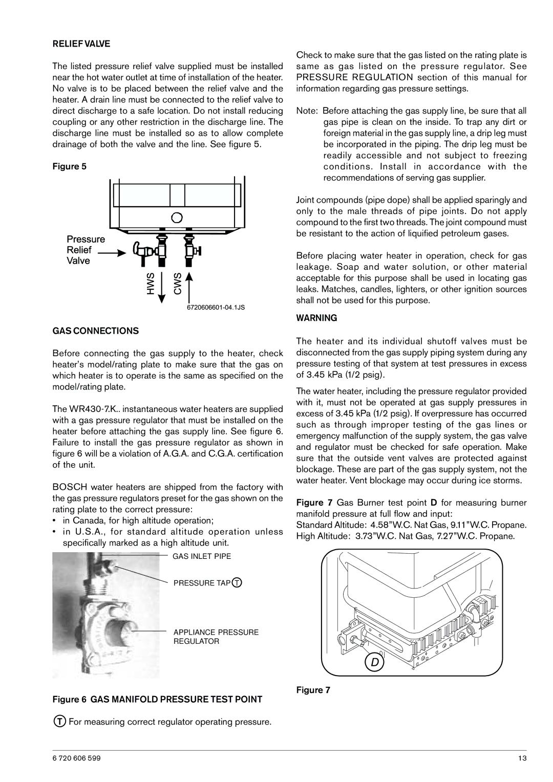
GAS INLET PIPE
PRESSURE TAP T
APPLIANCE PRESSURE
REGULATOR
Check to make sure that the gas listed on the rating plate is same as gas listed on the pressure regulator. See PRESSURE REGULATION section of this manual for information regarding gas pressure settings.
Note: Before attaching the gas supply line, be sure that all gas pipe is clean on the inside. To trap any dirt or foreign material in the gas supply line, a drip leg must be incorporated in the piping. The drip leg must be readily accessible and not subject to freezing conditions. Install in accordance with the recommendations of serving gas supplier.
Joint compounds (pipe dope) shall be applied sparingly and only to the male threads of pipe joints. Do not apply compound to the first two threads. The joint compound must be resistant to the action of liquified petroleum gases.
Before placing water heater in operation, check for gas leakage. Soap and water solution, or other material acceptable for this purpose shall be used in locating gas leaks. Matches, candles, lighters, or other ignition sources shall not be used for this purpose.
WARNING
The heater and its individual shutoff valves must be disconnected from the gas supply piping system during any pressure testing of that system at test pressures in excess of 3.45 kPa (1/2 psig).
The water heater, including the pressure regulator provided with it, must not be operated at gas supply pressures in excess of 3.45 kPa (1/2 psig). If overpressure has occurred such as through improper testing of the gas lines or emergency malfunction of the supply system, the gas valve and regulator must be checked for safe operation. Make sure that the outside vent valves are protected against blockage. These are part of the gas supply system, not the water heater. Vent blockage may occur during ice storms.
Figure 7 Gas Burner test point D for measuring burner manifold pressure at full flow and input:
Standard Altitude: 4.58”W.C. Nat Gas, 9.11”W.C. Propane.
High Altitude: 3.73”W.C. Nat Gas, 7.27”W.C. Propane.
Figure 7
Figure 6 GAS MANIFOLD PRESSURE TEST POINT
TFor measuring correct regulator operating pressure.
6 720 606 599 | 13 |