For either a confined or unconfined space in a building of tight construction with inadequate infiltration, air must be drawn from the outdoors or from spaces that freely communicate with the outdoors. Two permanent openings located as indicated are to be provided as follows:
1.When communicating with outdoors directly or by means of vertical ducts, each opening shall have a free area of not less than one square inch per 4,000 BTU/Hr. of total input of all appliances in the space.
2.When communicating with outdoors by means of horizontal ducts, each opening shall have a free area of not less than one square inch per 2,000 BTU/Hr. of total input of all appliances in the space.
For detailed requirements see:
•in Canada,
•in U.S.A.,
WARNING!
1.Flammable materials, gasoline, pressurized containers, or any other items or articles that are potentially fire hazards must never be placed on or adjacent to the heater. The appliance area must be kept free of all combustible materials, gasoline and other flammable vapors and liquids.
2.Do not obstruct the flow of combustion and ventilation air to the appliance.
CLEARANCE
The
mmfrom back, 102 mm (4 inches) from sides, 305 mm (12 inches) from top and bottom, and 102 mm (4 inches) from front. A minimum of 305 mm (12 inches) shall be allowed for maintenance of serviceable parts. Clearance from vent is dependent upon the clearance rating of the venting material used; see venting page 6.
Warning!
Check Flue Gas Safety Device good functioning, please proceed as explained in "Flue gas safety device" page 16.
MOUNTING
The
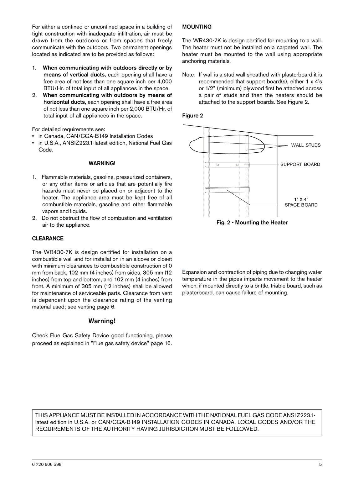
Note: If wall is a stud wall sheathed with plasterboard it is recommended that support board(s), either 1 x 4's or 1/2” (minimum) plywood first be attached across a pair of studs and then the heaters should be attached to the support boards. See Figure 2.
Figure 2
WALL STUDS
SUPPORT BOARD
1” X 4”
SPACE BOARD
Fig. 2 - Mounting the Heater
Expansion and contraction of piping due to changing water temperature in the pipes imparts movement to the heater which, if mounted directly to a brittle, friable board, such as plasterboard, can cause failure of mounting.
THIS APPLIANCE MUST BE INSTALLED IN ACCORDANCE WITH THE NATIONAL FUEL GAS CODE ANSI Z223.1- latest edition in U.S.A. or CAN/CGA-B149 INSTALLATION CODES IN CANADA. LOCAL CODES AND/OR THE REQUIREMENTS OF THE AUTHORITY HAVING JURISDICTION MUST BE FOLLOWED.
6 720 606 599 | 5 |
