Bosch POWER VENTING SYSTEM
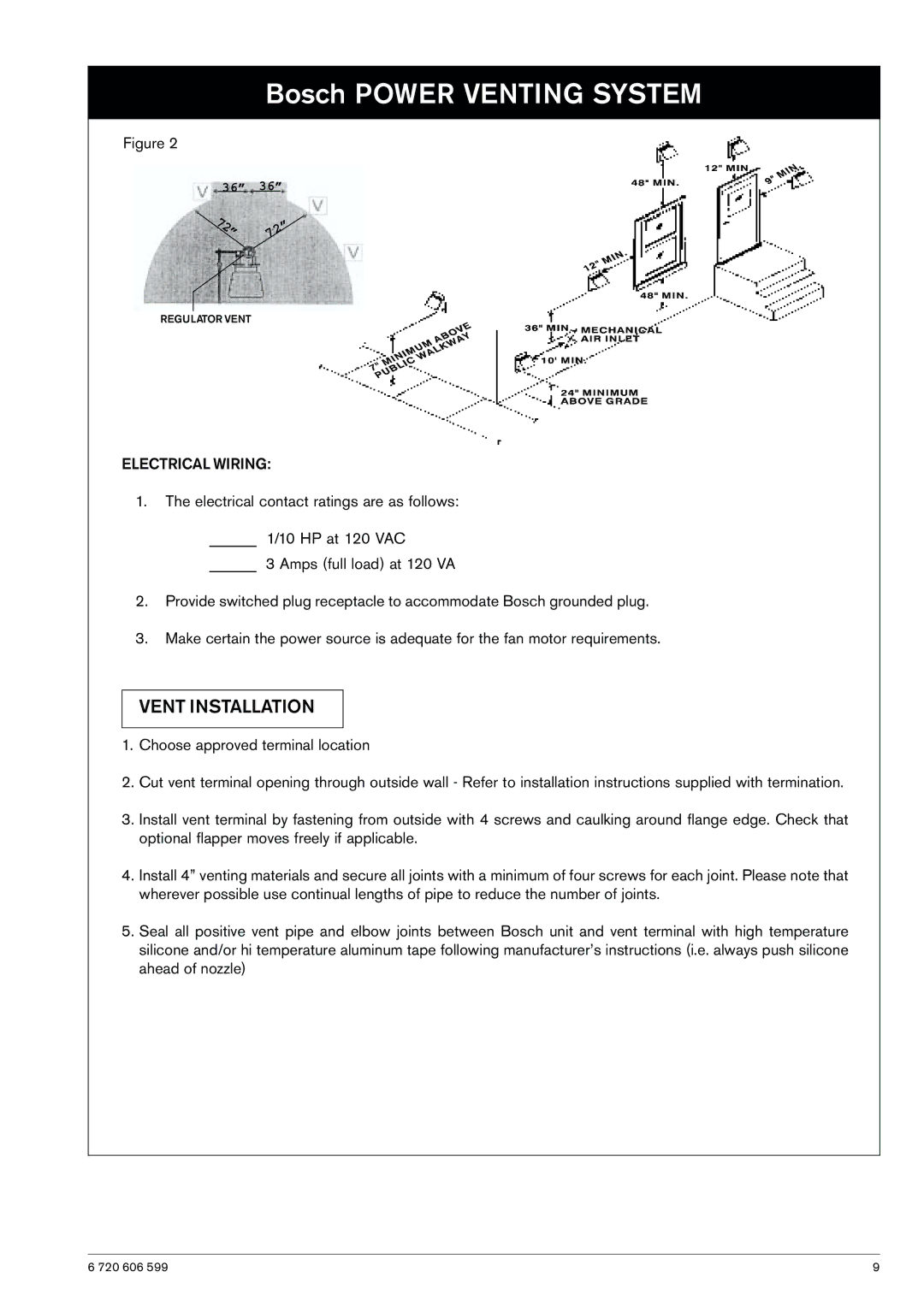
Figure 2
36”
7 |
|
2 | |
| ” |
36”
72”
REGULATOR VENT
ELECTRICAL WIRING:
1.The electrical contact ratings are as follows:
______ 1/10 HP at 120 VAC
______ 3 Amps (full load) at 120 VA
2.Provide switched plug receptacle to accommodate Bosch grounded plug.
3.Make certain the power source is adequate for the fan motor requirements.
VENT INSTALLATION
1.Choose approved terminal location
2.Cut vent terminal opening through outside wall - Refer to installation instructions supplied with termination.
3.Install vent terminal by fastening from outside with 4 screws and caulking around flange edge. Check that optional flapper moves freely if applicable.
4.Install 4” venting materials and secure all joints with a minimum of four screws for each joint. Please note that wherever possible use continual lengths of pipe to reduce the number of joints.
5.Seal all positive vent pipe and elbow joints between Bosch unit and vent terminal with high temperature silicone and/or hi temperature aluminum tape following manufacturer’s instructions (i.e. always push silicone ahead of nozzle)
6 720 606 599 | 9 |