Bowers & Wilkins 4000 owner manual Introduction, Unpacking figure, A tour of the subwoofer figure

Models: 4000

1 42
Download 42 pages 7.49 Kb
Page 8
Image 8

Introduction

Thank you for purchasing the B&W ASW4000 Active Subwoofer.

Since its foundation in 1966, the continuing philosophy of B&W has been the quest for perfect sound reproduction. Inspired by the company’s founder, the late John Bowers, this quest has entailed not only high investment in audio technology and innovation but also an abiding appreciation of music and the demands of film sound to ensure that the technology is put to maximum effect.

The ASW4000 has been designed for Home Theatre installations and to augment the bass performance of ‘full range’ speakers in stereo audio use. Adding the subwoofer to your system not only extends the bass to lower frequencies, it improves the midrange clarity by reducing the low-frequency demands on your existing speakers.

The subwoofer is magnetically shielded for use close to a television screen.

Please read through this manual fully before using the subwoofer. All sound installations require some planning and experimentation if you are to get the best out of the products used and this manual will guide you in this process.

As the subwoofer is connected to the electricity power supply, it is important that you familiarise yourself with the safety instructions and heed all warnings.

Keep this manual in a safe place for future reference.

B&W loudspeakers are distributed to over 60 countries world-wide and we maintain an international network of carefully chosen and dedicated distributors. If you have a problem which your dealer cannot resolve, our distributors will be more than willing to assist you.

Unpacking (figure 1)

The easiest way to unpack the subwoofer and avoid damage is as follows:

Open the carton flaps right back and invert the carton and contents.

Lift the carton away from the product.

We recommend that you retain the packaging for future use.

In addition to this manual, the carton should contain:

1 Subwoofer

1 Accessory pack containing:

4 Spikes with lock nuts

4 Self-adhesive rubber feet

1 Phono ‘T’-splitter plug

A tour of the subwoofer (figure 2)

1 Heatsink

2 Line level connectors

3 Speaker level connectors

4Low-pass filter frequency control (line input)

5 Volume control (line input)

6 Decoder input

7 Volume control (decoder input)

8 Equalisation switch (decoder input)

9 Phase switch

10On/Auto/Off switch

11Mains input socket

12Voltage selector/indicator

13Fuseholder

14Power/Standby indicator

15Toroidal mains transformer housing

Positioning the subwoofer

Because the subwoofer produces only low- frequency sounds, positioning is less critical in some respects compared with full-range speakers. Directional information is much less precise and you have more choice where to place the speakers to good effect. This said, best results are obtained if the subwoofer is placed between the satellite speakers or in the vicinity of one of them. If you use two subwoofers, it is best to put one near each satellite speaker.

Placing the subwoofer behind the listeners, even in surround sound installations, generally gives inferior imaging; but may be an acceptable compromise if domestic considerations dictate.

As with all speakers, the proximity of room boundaries affects the sound. Bass is generally increased as more surfaces come into close proximity with the speakers. Unlike full-range speakers, however, you can always restore the correct overall system balance by adjusting the volume level of the subwoofer. The more boost you get from the room, the less hard the speaker has to work; but there is a down side. Corner positions often excite more low-frequency room resonances, making the bass more uneven with frequency. There is no substitute for experiment as all rooms behave differently, so try the subwoofer in a variety of positions before making a final decision. A piece of music with a bass line ascending or descending the musical scale is useful for assessing the smoothness of the bass response. Listen for exaggerated or quiet notes. Having a separate subwoofer does enable you to optimise for room resonances independently from siting the satellite speakers for best imaging.

If the subwoofer is to be used in a confined space (eg in custom furniture), the space must be ventilated to allow sufficient air to circulate and cool the unit. Ask your dealer for advice.

The subwoofer is supplied with four spike feet. The spikes pierce through carpet pile, giving a firm support directly to the floor surface without crushing the pile. When fitting spikes, first screw the lock nuts fully onto the spikes, then screw the spikes fully onto the threaded inserts in the base of the cabinet. If the unit rocks, loosen the relevant two opposing spikes until the support is firm, then re-tighten the lock nuts to the inserts.

If the unit is to be placed on a vulnerable surface, either place a protective disc under each spike or fit the four rubber pads in place of the spikes.

Electrical connections

Disconnect all sound system equipment from the power supply until the signal connections have been made and checked. This avoids the risk of damage whilst connections are made or broken.

The function of the subwoofer is to receive signals from the amplification chain and, where necessary split the signal into low bass and higher frequencies and feed the latter back out to the satellite speakers. Left and right channel inputs may be combined into a single mono low bass feed to the subwoofer drive unit if required.

The subwoofer will input and output both line level signals via the RCA Phono sockets and speaker level signals via the binding posts located on the back panel, giving a flexible choice of connection methods. However, you must not use a mixture of line level and speaker level connections in the same installation. If you have a choice between line level and speaker level connections, choose line level.

The subwoofer also has a dedicated decoder input, which is automatically selected if a signal is present on this input. If no signal is detected on this input for approximately 20 seconds, the subwoofer will switch to the line/speaker level inputs.

Decoder volume and equalisation are set by separate controls from the line and speaker inputs, for ease of installation.

Use the following table to select the correct wiring method for your installation:

Application: Home Theatre

Decoder with separate power amplifiers:

a With subwoofer output: Connections: fig. 3

b No subwoofer output: Connections: fig. 4

Decoder with integrated power amplifiers:

a With subwoofer output: Connections: fig. 5

b No subwoofer output: Connections: fig. 6

Application: Stereo Audio

Separate pre- & power amplifiers:

aOne or more subwoofers with output combined into a single mono signal: Connections: fig. 7

bTwo subwoofers with separate left and right signals: Connections: fig. 8

Integrated amplifier:

a One or more subwoofers with output combined into a single mono signal: Connections: fig. 9

bTwo subwoofers with separate left and right signals: Connections: fig. 10

Using more than one subwoofer
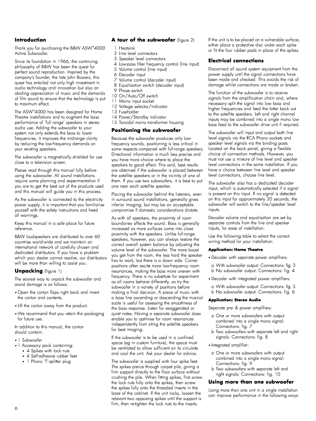
Using more than one unit in a single installation can improve performance in the following ways:

6

Page 8
Image 8
Bowers & Wilkins 4000 Introduction, Unpacking figure, A tour of the subwoofer figure, Positioning the subwoofer