Βρυτε Μαγνυμ | Page 37 |
|
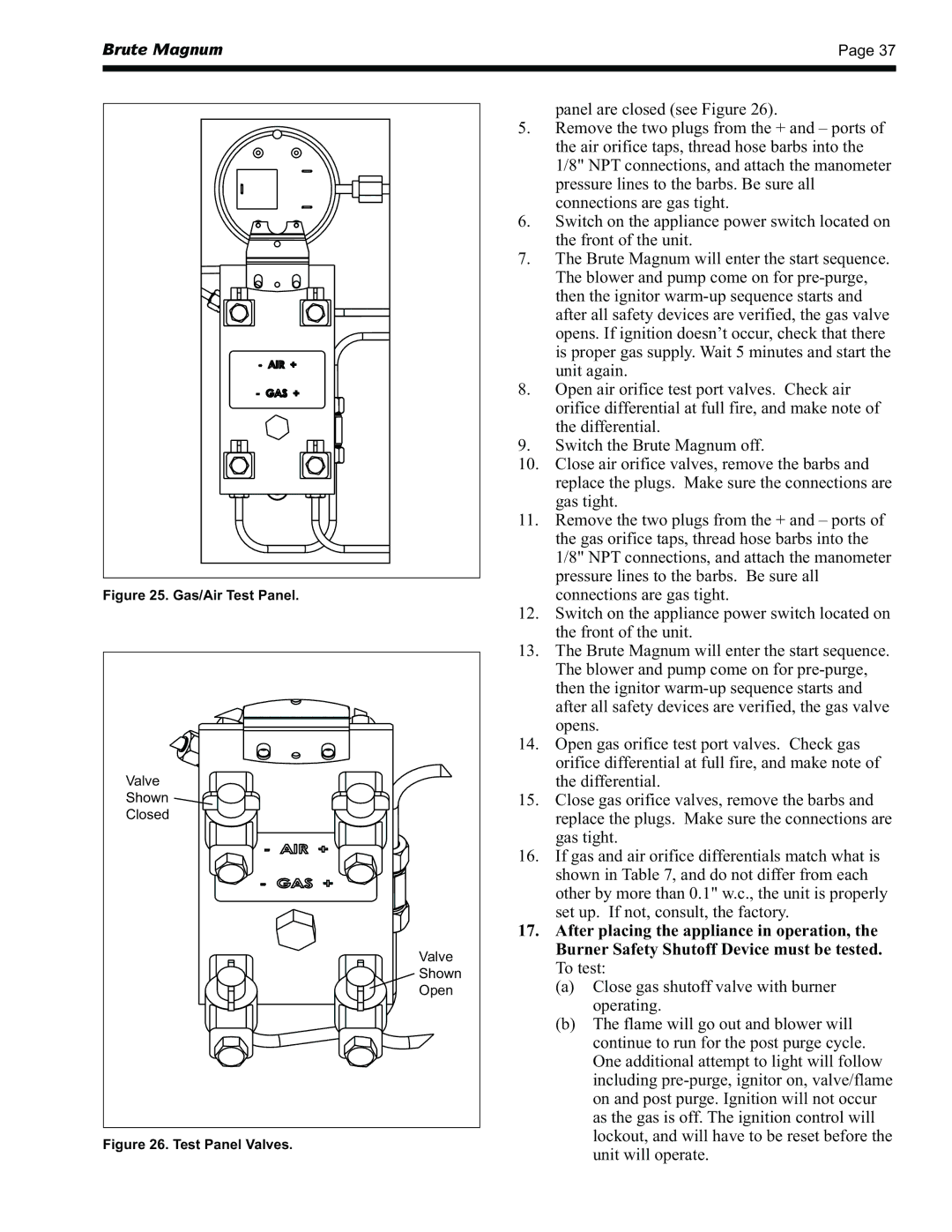
Figure 25. Gas/Air Test Panel.
Valve
Shown ![]()
![]()
Closed
Valve
Shown
Open
Figure 26. Test Panel Valves.
panel are closed (see Figure 26).
5.Remove the two plugs from the + and – ports of the air orifice taps, thread hose barbs into the 1/8" NPT connections, and attach the manometer pressure lines to the barbs. Be sure all connections are gas tight.
6.Switch on the appliance power switch located on the front of the unit.
7.The Brute Magnum will enter the start sequence. The blower and pump come on for
8.Open air orifice test port valves. Check air orifice differential at full fire, and make note of the differential.
9.Switch the Brute Magnum off.
10.Close air orifice valves, remove the barbs and replace the plugs. Make sure the connections are gas tight.
11.Remove the two plugs from the + and – ports of the gas orifice taps, thread hose barbs into the 1/8" NPT connections, and attach the manometer pressure lines to the barbs. Be sure all connections are gas tight.
12.Switch on the appliance power switch located on the front of the unit.
13.The Brute Magnum will enter the start sequence. The blower and pump come on for
14.Open gas orifice test port valves. Check gas orifice differential at full fire, and make note of the differential.
15.Close gas orifice valves, remove the barbs and replace the plugs. Make sure the connections are gas tight.
16.If gas and air orifice differentials match what is shown in Table 7, and do not differ from each other by more than 0.1" w.c., the unit is properly set up. If not, consult, the factory.
17.After placing the appliance in operation, the Burner Safety Shutoff Device must be tested. To test:
(a)Close gas shutoff valve with burner operating.
(b)The flame will go out and blower will continue to run for the post purge cycle. One additional attempt to light will follow including
