Manuals
/
Bradford-White Corp
/
Household Appliance
/
Boiler
Bradford-White Corp
BRHHH, BRHHV
warranty
Jacket Components
Models:
BRHHV
BRHHH
1
55
56
56
Download
56 pages
2.76 Kb
49
50
51
52
53
54
55
56
Troubleshooting
Parts list
Wiring Diagrams
Warranty
Maintenance
Auto Reset Temperature Limit
Differential Setting
Temperature Control Boiler
Replacement Parts
Flow Switch
Page 55
Image 55
Βρυτε Μαγνυμ
Page 55
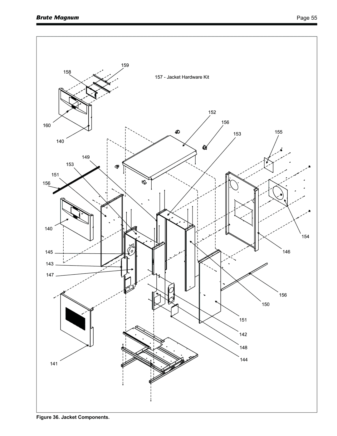
Figure 36. Jacket Components.
Page 54
Page 56
Page 55
Image 55
Page 54
Page 56
Contents
Βρυτε Μαγνυμ
Βραδφορδ Ωηιτε Χορπ
Replacement Parts
Table of Contents
Maintenance
Troubleshooting
List of Figures
List of Tables
Model Designation
General Information
Introduction
Model Identification
Dimensions
Warranty
Locating the Appliance
Inches 91cm horizontally
Intake Combustion Air
Venting and Combustion AIR
Combustion Air
Combustion Air From Room
Locating Vent & Combustion Air Terminals
Venting
Horizontal Vent Terminal
Combustion Air and Vent Through Side Wall
From Massachusetts Rules and Regulations 248 CMR
Installation of Carbon Monoxide Detectors
Vertical Combustion Air Terminal
Common Vent Test Boilers
Side Wall Combustion Air Terminal
Vertical Vent Terminal
Distance from Gas Meter or Last Stage Regulator
GAS Supply and Piping
4A.1 Heating System Piping Hot Supply Connections Boiler
Water Connections Brute Magnum Boiler
4A.2 Cold Water Make-Up Boiler
4B.2 Hot Water Supply Piping Water Heater
Water Connections Brute Magnum Water Heater
4A.3 Freeze Protection Boiler
4B.1 Water System Piping Water Heater
Hydronic Piping Multiple Boilers
4B.3 Water Flow Requirements Water Heater
Hydronic Piping Multiple Boilers Alternate
4B.4 Combined Water potable Heating and Space Heating
Hydronic Piping One Boiler, Multi-Temperature System
4B.5 Freeze Protection Water Heater
Heater or in the pipes in the system. When water
Water Heater Piping One Heater, One Tank
Water Heater Piping Multiple Heaters, One Tank
Water Heater Piping One Heater, Multiple Tanks
Water Heater Piping Multiple Heaters, Multiple Tanks
Electrical Connections
Main Power
Temperature Control Boiler
Temperature Control Water Heater
Differential Setting
Temperature Control Features
Internal Water Heater Temperature Control
Temperature Setpoint
Throttling Range
Offset
Integration Constant
Minimum Output Setting
Control Parameter Possible Interference
Mixing System and Control
External Control Connections
Wiring Diagrams
Wiring Diagram, Size 1200, Standard and Codes a and F
Βρυτε Μαγνυμ
Wiring Diagram, Size 1200, Code B
Wiring Diagram, Sizes 1600, 2000 and 2400, Code B
Wiring Schematic, Model 1200, Standard and Codes a and F
Wiring Schematic, Model 1200, Code B
Operating Instructions
Operating the Burner and Set Up
Filling the Boiler System
Gas/Air Test Panel
Shutting Down the Brute Magnum
Maintenance
System Maintenance
Appliance Maintenance Component Description
Gas Trains
Filter
Burner
Modulating Gas Valve
Mixing Control
Safety Gas Valve
Manual Reset High Limit Control
Auto Reset Temperature Limit
Ignition Control
Ignitor / Flame Sensor Assembly
Flow Switch
Mixing Actuator
Sequence of Operation
Troubleshooting
Motorized Safety Valve
Gas Pressure Switches
Resolving Lockouts
Delayed Ignition Possible Causes
Short Cycling Boiler
Short Cycling Water Heater
Replacement Parts
High Gas Consumption
Combustion Components See Figure
Parts List
Electrical Components See Figure
Jacket See Figure
Combustion Components
Gas Train/Combustion Air Components
Gas Train Components
Electrical Components
Heat Exchanger / Water Path Components
Heat Exchanger / Water Path Components
Jacket Components
Litho in U.S.A. Bradford White 1102 Document
Top
Page
Image
Contents