Page 4ΒΡΑΔΦΟΡΔ ΩΗΙΤΕ ΧΟΡΠ.
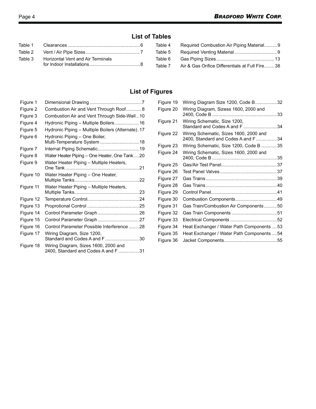
List of Tables
Table 1 | Clearances | 6 | Table 4 | Required Combustion Air Piping Material | ..........9 |
Table 2 | Vent / Air Pipe Sizes | 7 | Table 5 | Required Venting Material | 9 |
Table 3 | Horizontal Vent and Air Terminals |
| Table 6 | Gas Piping Sizes | 13 |
| for Indoor Installations | 8 | Table 7 | Air & Gas Orifice Differentials at Full Fire | 38 |
|
|
|
List of Figures
Figure 1 | Dimensional Drawing | 7 | Figure 19 | Wiring Diagram Size 1200, Code B | 32 | |
Figure 2 | Combustion Air and Vent Through Roof | 8 | Figure 20 | Wiring Diagram, Sizess 1600, 2000 and |
| |
Figure 3 | Combustion Air and Vent Through | 10 |
| 2400, Code B | 33 | |
Figure 21 Wiring Schematic, Size 1200, |
| |||||
Figure 4 | Hydronic Piping – Multiple Boilers | 16 |
| |||
| Standard and Codes A and F | 34 | ||||
Figure 5 | Hydronic Piping – Multiple Boilers (Alternate).17 |
| ||||
Figure 22 Wiring Schematic, Sizes 1600, 2000 and |
| |||||
Figure 6 | Hydronic Piping – One Boiler, |
|
| |||
|
| 2400, Standard and Codes A and F | 34 | |||
|
| 18 |
| |||
| Figure 23 Wiring Schematic, Size 1200, Code B | 35 | ||||
Figure 7 | Internal Piping Schematic | 19 | ||||
Figure 24 Wiring Schematic, Sizes 1600, 2000 and |
| |||||
Figure 8 | Water Heater Piping – One Heater, One Tank.... | 20 |
| |||
| 2400, Code B | 35 | ||||
Figure 9 | Water Heater Piping – Multiple Heaters, |
|
| |||
| Figure 25 Gas/Air Test Panel | 37 | ||||
| One Tank | 21 | ||||
| Figure 26 Test Panel Valves | 37 | ||||
Figure 10 | Water Heater Piping – One Heater, |
| ||||
| Figure 27 | Gas Trains | 39 | |||
| Multiple Tanks | 22 | ||||
| Figure 28 | Gas Trains | 40 | |||
Figure 11 | Water Heater Piping – Multiple Heaters, |
| ||||
| Multiple Tanks | 23 | Figure 29 | Control Panel | 41 | |
Figure 12 | Temperature Control | 24 | Figure 30 | Combustion Components | 49 | |
Figure 13 | Proprotional Control | 25 | Figure 31 | Gas Train/Combustion Air Components | 50 | |
Figure 14 | Control Parameter Graph | 26 | Figure 32 | Gas Train Components | 51 | |
Figure 15 | Control Parameter Graph | 27 | Figure 33 | Electrical Components | 52 | |
Figure 16 | Control Parameter Possible Interference | 28 | Figure 34 | Heat Exchanger / Water Path Components .... | 53 | |
Figure 17 | Wiring Diagram, Size 1200, |
| Figure 35 Heat Exchanger / Water Path Components .... | 54 | ||
| Standard and Codes A and F | 30 | Figure 36 | Jacket Components | 55 | |
Figure 18 | Wiring Diagram, Sizes 1600, 2000 and |
| ||||
|
|
|
| |||
| 2400, Standard and Codes A and F | 31 |
|
|
| |
