Internet Version for Reference Only
HIGH INPUT DIRECT VENT INSTALLATION & OPERATING INSTRUCTION MANUAL
FOR YOUR SAFETY
DIRECT VENT GAS WATER HEATER
Internet Version for Reference Only
CONGRATULATIONS
TABLE OF CONTENTS
INSTALLATION
PARTS LIST DRAWINGS
INSTALLATIONS FOR POTABLE WATER AND SPACE
Internet Version for Reference Only
GENERAL INFORMATION
DANGER
INSTALLATION
Internet Version for Reference Only
CIRCUMSTANCES SHALL FLAMMABLE MATERIALS, SUCH AS
GASOLINE OR PAINT THINNER BE USED OR STORED IN THE
COVERED BY THE WARRANTY. DO NOT OPERATE THE WATER
Installation Locating The Water Heater continued
Internet Version for Reference Only
HEATER CAUSED BY EXPOSURE TO CORROSIVE VAPORS IS NOT
Internet Version for Reference Only
Most people recognize this odor as a “sulfur” or “rotten egg” smell
Installation continued
Internet Version for Reference Only
MINIMUM CLEARANCES
OPTIONAL DIRECT VENT-AIR INTAKE TERMINAL GUARD
Figure 1A
Installation Minimum Clearances continued
Internet Version for Reference Only
Figure 1B
Installation Minimum Clearances continued
Internet Version for Reference Only
Installation Minimum Clearances continued
Internet Version for Reference Only
DO NOT install any damaged vent-air intake system components
Contact the manufacturer of the water heater for replacement parts
Internet Version for Reference Only
VENTING
Installation Venting continued
Internet Version for Reference Only
Internet Version for Reference Only
HORIZONTAL AND VERTICAL VENT-AIR INTAKE LENGTHS
Internet Version for Reference Only
Table A
no addl
order
Internet Version for Reference Only
Do not install any damaged vent-air intake system components
Contact the manufacturer of the water heater for replacement parts
Internet Version for Reference Only
Tape Measure Drill
Internet Version for Reference Only
See Figure
Internet Version for Reference Only
Internet Version for Reference Only
7. Extend the four 4 inch 10.2 cm diameter telescopic tube to its maximum length and slide the backing plate over it. Place the large end of the four 4 inch 10.2 cm diameter telescopic tube through the hole in the outside wall. Insert the smaller end of the four 4 inch diameter 10.2 cm telescopic tube into the flared end of the four 4 inch 10.2 cm diameter elbow, one 1 inch 2.5 cm or until seated. Drill three
8. Extend the six 6 inch 15.2 cm diameter telescopic tube to its maximum length. Place the large end of the six 6 inch 15.2 cm diameter telescopic tube over the collar on the outer wall mounting plate. Drill three 3 1/8 inch 3.2 mm diameter holes, 120o apart, through the six 6 inch 15.2 cm diameter telescopic tube into the collar on the outer wall mounting plate. Fasten with three 3 #8 sheet metal screws supplied. Using the supplied special RTV silicone sealant, apply a sufficient amount to seal the joint See Figure
Internet Version for Reference Only
Internet Version for Reference Only
9. From outside the building, slide the six 6 inch 15.2 cm diameter telescopic tube through the opening in the wall until the outer wall mounting plate is flush with the wall See Figure
11. From inside the building, slide the backing plate over the six 6 inch 15.2 cm diameter telescopic tube until it is flush with the wall. Adjust the length of the six 6 inch 15.2 cm diameter telescopic tube and insert the end into the flared end of the six 6 inch 15.2 cm diameter elbow one 1 inch 2.5 cm or until seated. Drill three 3 1/8 inch 3.2 mm diameter holes, 120o apart, through the six 6 inch 15.2 cm diameter elbow into the six 6 inch 15.2 cm diameter telescopic tube and through the tubes where the small and large sections overlap. Fasten with three 3 #8 sheet metal screws supplied. Using the supplied special RTV silicone sealant, apply a sufficient amount to seal all joints See Figure
Internet Version for Reference Only
Internet Version for Reference Only
Note BEFORE PROCEEDING WITH THE INSTALLATION, CLOSE THE
Internet Version for Reference Only
WATER CONNECTIONS
MAIN WATER SUPPLY VALVE
Installation Water Connections continued
Internet Version for Reference Only
FAILURE TO INSTALL AND MAINTAIN A NEW, LISTED 3/4” X 3/4”
TEMPERATURE AND PRESSURE RELIEF VALVE WILL RELEASE
FROM EXCESSIVE TEMPERATURES AND PRESSURES
Internet Version for Reference Only
Installation Water Connections continued
Internet Version for Reference Only
OPEN FLAME FOR TESTING
Internet Version for Reference Only
GENERAL OPERATION
Internet Version for Reference Only
CIRCUMSTANCES SHALL FLAMMABLE MATERIALS, SUCH AS
GASOLINE OR PAINT THINNER BE USED OR STORED IN THE
Internet Version for Reference Only
WARNING If you do not follow these instructions exactly, a fire or
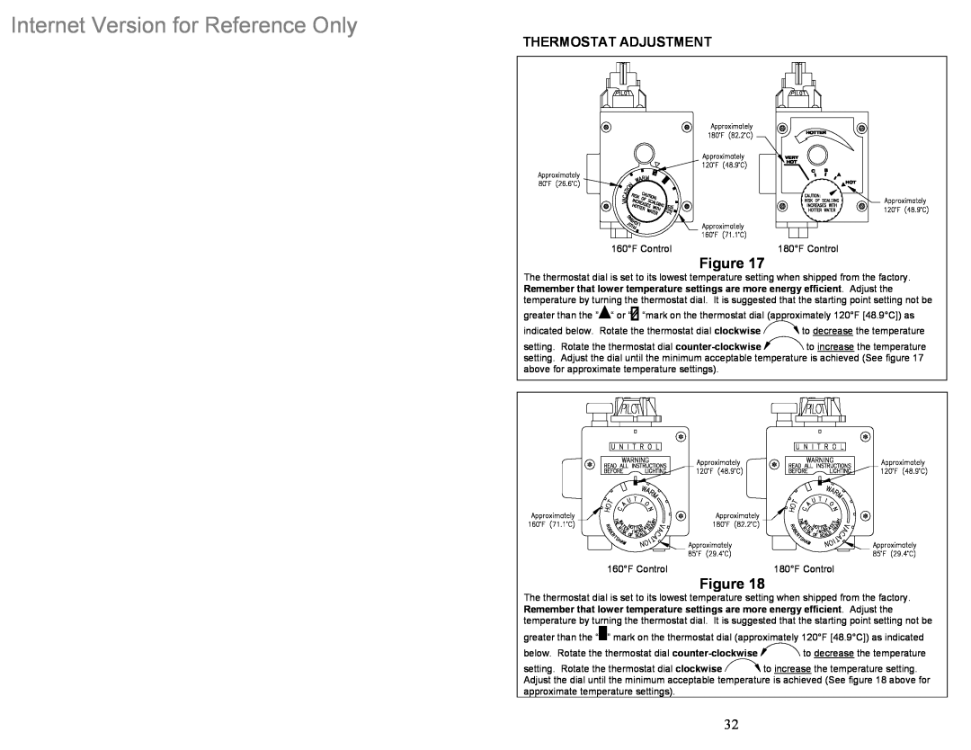
THERMOSTAT ADJUSTMENT
Internet Version for Reference Only
Burner Flame Check
Internet Version for Reference Only
DANGER
MAINTENANCE
Internet Version for Reference Only
CIRCUMSTANCES SHALL FLAMMABLE MATERIALS, SUCH AS
GASOLINE OR PAINT THINNER BE USED OR STORED IN THE
WARNING! THIS WATER MAY BE HOT
Maintenance continued
Internet Version for Reference Only
OF TIME THAT PARTS AND THE WATER HEATER ARE WARRANTED
READ THE WARRANTY FOR A FULL EXPLANATION OF THE LENGTH
Internet Version for Reference Only
PARTS LIST
Internet Version for Reference Only
Certain Models
Optional Not Shown
Internet Version for Reference Only
DIRECT VENT WATER HEATER
Internet Version for Reference Only
VENT-AIR INTAKE KITS
SUITABLE FOR WATER POTABLE HEATING AND SPACE HEATING
THE FOLLOWING INSTRUCTIONS ARE FOR INSTALLATION OF GAS WATER HEATERS
Internet Version for Reference Only