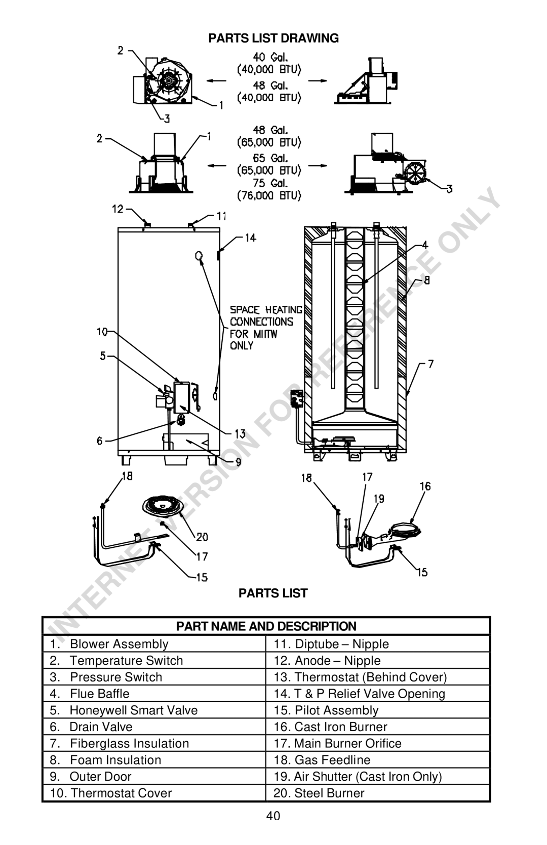
PARTS LIST DRAWING
PARTS LIST
PART NAME AND DESCRIPTION
1. | Blower Assembly | 11. Diptube – Nipple | |
2. | Temperature Switch | 12. | Anode – Nipple |
3. | Pressure Switch | 13. | Thermostat (Behind Cover) |
4. | Flue Baffle | 14. | T & P Relief Valve Opening |
5. | Honeywell Smart Valve | 15. | Pilot Assembly |
6. | Drain Valve | 16. | Cast Iron Burner |
7. | Fiberglass Insulation | 17. | Main Burner Orifice |
8. | Foam Insulation | 18. | Gas Feedline |
9. | Outer Door | 19. Air Shutter (Cast Iron Only) | |
10. Thermostat Cover | 20. Steel Burner | ||
40