Braun Corporation FMVSS No. 403 Quick Reference Installation Sheet 32494
2 | Secure Lift |
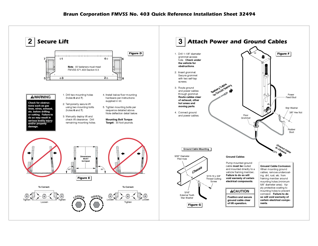
3 | Attach Power and Ground Cables |
7 | 1 | 4 |
|
| Note. All fasteners must meet |
|
| FMVSS 571.403 Section 6.3. |
5 | 3 | 2 |
Figure D 

6
![]()
![]() 8
8
1. | Drill |
| grommet access |
| hole. Check under |
| the vehicle for |
| obstructions. |
2. | Insert grommet. |
| Secure grommet |
| with two |
| screws. |
Figure F |
![]()
![]()
![]() WARNING
WARNING
Check for obstruc- tions such as gas lines, wires, exhaust, etc. before drilling or cutting. Failure to do so may result in serious bodily injury and/or property damage.
1.Drill two mounting holes (holes 6 and 7).
2.Temporarily secure lift using two mounting bolts (holes 6 and 7).
3.Manually deploy lift and check lift clearance. Drill remaining mounting holes.
4.Install below floor mounting hardware per instructions supplied in kit.
5.Tighten mounting bolts per sequence detailed above.
Note deflection detail below.
Mounting Bolt Torque Target: 30 foot pounds.
3. | Route ground |
| and power cables |
| through grommet. |
| Route cables clear |
| of exhaust, other |
| hot areas and |
| moving parts. |
4. | Connect ground |
| and power cables. |
CableSentry
BatteryCircuit
to
Floor
Grommet
Power
![]() Feed Stud
Feed Stud
Star Washer
![]() 3/8" Hex Nut
3/8" Hex Nut
Rubber
Boot
TIGHTEN
Tighten ![]()
![]()
To Correct:
OS | EN |
LO |
Loosen
| Dimensions |
| MUST |
| be Equal |
90 | 90 |
Figure E |
To Correct:
TIGHTEN |
| OS | E |
| H | T | E | LOOSEN | TIGHTEN |
|
|
|
|
| |||||
|
| G |
|
| |||||
| O | I |
|
|
|
| |||
Tighten | L |
| N | T |
|
| N | Loosen |
|
|
|
|
|
|
|
| Tighten | ||
|
|
|
|
|
|
|
|
| |
OS | EN |
LO |
![]() Loosen
Loosen
Ground Cable Mounting
9/32" Diameter
Pilot Hole
Chassis
5/16"
External Tooth
Star Washer
Figure G
|
|
|
| to |
|
|
|
|
| Ground | Cable |
|
|
|
| Chassis | |
| Ground Cables |
|
| ||
| Pump mounted ground |
|
| ||
| cable must be routed | Ground Cable Corrosion: | |||
| and mounted directly to a | When mounting ground | |||
| vehicle framing member. | cables, remove undercoat- | |||
| Failure to do so will | ing, dirt, rust, etc. from | |||
| void warranty of certain | framing member around | |||
| electrical components. | mounting holes (minimum | |||
|
|
|
| 5/8” diameter area). Ap- | |
|
|
|
| ply protective coating to | |
| CAUTION |
|
| mounting holes to prevent | |
|
|
|
| corrosion. Failure to do | |
| Position and secure |
|
| ||
|
|
| so will void warranty of | ||
| ground cable clear |
|
| certain electrical compo- | |
| of lift operation. |
|
| nents. |
|
|
|
|
|
|
|