Braun Corporation FMVSS No. 403 Quick Reference Installation Sheet 32494
4 | Connect Interlocks |
5 | Adjust Platform Angle |
Vehicle and Lift Interlocks
The pump module is equipped with a lift interface
To meet minimum NHTSA requirements, connect to vehicle interlock harness as outlined below (Steps
Optional Interlock Kits
Universal Interlock Kit 30940K is available for easy interface with vehicle OEM electronic signals.
Instrument Panel Display Kit 30938K provides an LED Panel Display that interfaces with Braun Universal Interlock Kit 30940K.
Detailed installation instructions are supplied with interlock kits.
Note: All Braun Corporation in- terlocks require a positive (+12V) Lift Stowed signal (Pin 7).
![]()
![]()
![]() WARNING
WARNING
Install and verify proper operation of all NHTSA mandated interlocks as specified. Failure to do so will result in a
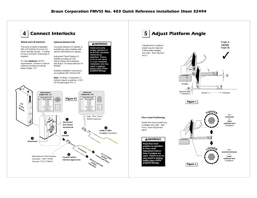
Adjustments to platform angle may be required if base plate wedges are used. See Figures I and J.
Angle A
equals
Angle B.
✓
A
Wedges
B
Approximately |
Lift
Pump
Module
PUMP MODULE
CONNECTOR - J21
NO. SIGNAL DEFINITION
1NOT USED
2NOT USED
3NOT USED
4NOT USED
5NOT USED
6VEHICLE SECURE (INPUT)
7LIFT STOWED (+12V)
8NOT USED
9LIFT STOWED (GND)
1![]()
![]() 2
2 ![]()
![]() 3
3
4![]()
![]() 5
5 ![]()
![]() 6
6
7![]()
![]() 8
8 ![]()
![]() 9
9
1 2 3
4 5 6
7 8 9
Figure H 

INTERLOCK
CONNECTOR - P21
NO. SIGNAL DEFINITION
1NOT USED
2NOT USED
3NOT USED
4NOT USED
5NOT USED
6VEHICLE SECURE (INPUT)
7LIFT STOWED (+12V)
8NOT USED
9LIFT STOWED (GND)
3![]()
![]() 2
2 ![]()
![]() 1
1
6![]()
![]() 5
5 ![]()
![]() 4
4
9![]()
![]() 8
8 ![]()
![]() 7
7
3 2 1
6 5 4
9 8 7
1” Clearance | Inboard | Outboard |
|
|
Figure I |
| H |
| |
G | T |
| |
E | |||
I | |||
T |
| N | |
2
Disconnect
As
Shipped

1 Disconnect and remove eye terminal
5
Connect
Note: Pins 7 and 9 300mA maximum.
3
Install 31798A
in cavity 7 (+) or 9
Floor Level Positioning:
Reset floor level positioning if wedges are used. See Floor Level Adjustment panel.
![]() WARNING
WARNING
Turn
clockwise
to
raise
outboard end
of platform
Reset floor level position as specified
| T | |
| o | |
| Interlock | |
Manufacturer’s Part Numbers | 4 | |
Connect vehicle | ||
Connector: AMP 172169 | ||
interlock signal wires | ||
Terminal:TYCO | ||
|
( | LIFT |
| |
Y | SIGNALOWED | ||
|
| ||
| ellow/Light | ||
VEHICLE |
|
| T |
|
| Blue) | |
SIGNAL |
| ||
|
| ||
(Grey/Red) | SECURE |
| |
in Floor Level Adjustment Instruc- tions if wedges are used. Failure to do so may result in serious bodily injury and/or property damage.
| OS |
| |
O | E | ||
L |
|
| N |
Figure J |
Turn
counterclockwise
to
lower
outboard end
of platform