Power Steering Conversion Kit | Installation Instructions |
NOTE: Read through these instructions, the SERVICE MANUAL, and OPERATOR’S MANUAL before beginning installation.
![]() WARNING
WARNING
Before beginning any service work turn off the PTO, set the parking brake, turn off the ignition, and disconnect the spark plug wire(s).
INITIAL ASSEMBLY
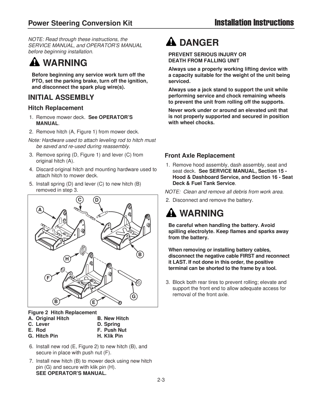
Hitch Replacement
1.Remove mower deck. See OPERATOR’S MANUAL.
2.Remove hitch (A, Figure 1) from mower deck.
Note: Hardware used to attach leveling rod to hitch must be saved and
3.Remove spring (D, Figure 1) and lever (C) from original hitch (A).
4.Discard original hitch and mounting hardware used to attach hitch to mower deck.
5.Install spring (D) and lever (C) to new hitch (B) removed in step 3.
C | D |
A |
|
H | B |
| |
F |
|
B | G |
E |
![]() DANGER
DANGER
PREVENT SERIOUS INJURY OR
DEATH FROM FALLING UNIT
Always use a properly working lifting device with a capacity suitable for the weight of the unit being serviced.
Always use a jack stand to support the unit while performing service and chock remaining wheels to prevent the unit from rolling off the supports.
Never work under or around an elevated unit that is not properly supported and secured in position with wheel chocks.
Front Axle Replacement
1.Remove hood assembly, dash assembly, seat and seat deck. See SERVICE MANUAL, Section 15 -
Hood & Dashboard Service, and Section 16 - Seat Deck & Fuel Tank Service.
NOTE: Clean and remove all debris from work area.
2. Disconnect and remove the battery.
![]() WARNING
WARNING
Be careful when handling the battery. Avoid spilling electrolyte. Keep flames and sparks away from the battery.
When removing or installing battery cables, disconnect the negative cable FIRST and reconnect it LAST. If not done in this order, the positive terminal can be shorted to the frame by a tool.
3.Block both rear tires to prevent rolling; elevate and support the front end to allow adequate access for removal of the front axle.
Figure 2 Hitch Replacement |
|
A. Original Hitch | B. New Hitch |
C. Lever | D. Spring |
E. Rod | F. Push Nut |
G. Hitch Pin | H. Klik Pin |
6.Install new rod (E, Figure 2) to new hitch (B), and secure in place with push nut (F).
7.Install new hitch (B) to mower deck using new hitch pin (G) and secure with klik pin (H).
SEE OPERATOR’S MANUAL.