Briggs & Stratton Power Products Home Standby Generator
Installation,
Fuel Pipe Sizing
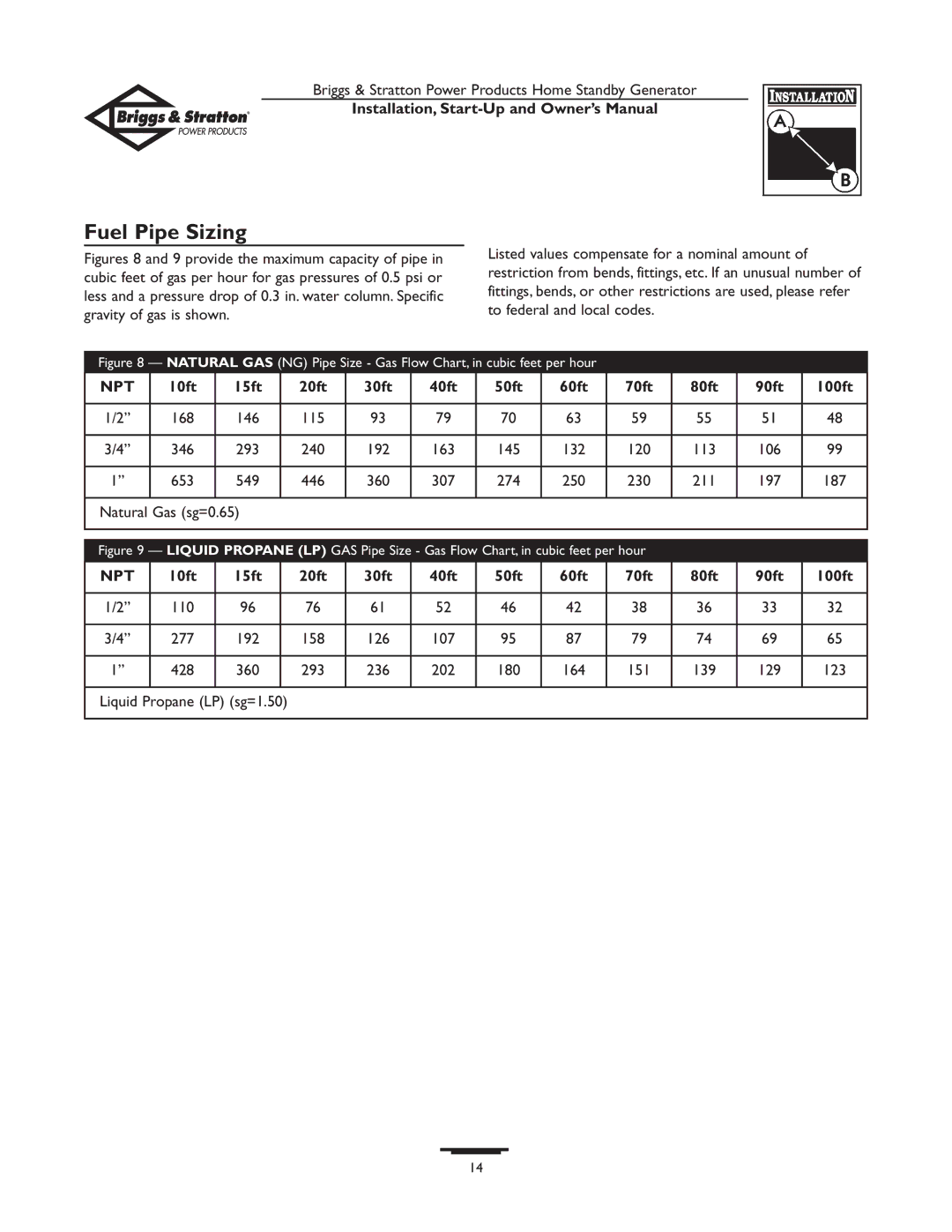
Figures 8 and 9 provide the maximum capacity of pipe in cubic feet of gas per hour for gas pressures of 0.5 psi or less and a pressure drop of 0.3 in. water column. Specific gravity of gas is shown.
Listed values compensate for a nominal amount of restriction from bends, fittings, etc. If an unusual number of fittings, bends, or other restrictions are used, please refer to federal and local codes.
Figure 8 — NATURAL GAS (NG) Pipe Size - Gas Flow Chart, in cubic feet per hour
NPT | 10ft | 15ft | 20ft | 30ft | 40ft | 50ft | 60ft | 70ft | 80ft | 90ft | 100ft |
|
|
|
|
|
|
|
|
|
|
|
|
1/2” | 168 | 146 | 115 | 93 | 79 | 70 | 63 | 59 | 55 | 51 | 48 |
|
|
|
|
|
|
|
|
|
|
|
|
3/4” | 346 | 293 | 240 | 192 | 163 | 145 | 132 | 120 | 113 | 106 | 99 |
|
|
|
|
|
|
|
|
|
|
|
|
1” | 653 | 549 | 446 | 360 | 307 | 274 | 250 | 230 | 211 | 197 | 187 |
|
|
|
|
|
|
|
|
|
|
|
|
Natural Gas (sg=0.65) |
|
|
|
|
|
|
|
|
| ||
|
|
|
| ||||||||
|
|
|
| ||||||||
Figure 9 — LIQUID PROPANE (LP) GAS Pipe Size - Gas Flow Chart, in cubic feet per hour |
|
|
| ||||||||
NPT | 10ft | 15ft | 20ft | 30ft | 40ft | 50ft | 60ft | 70ft | 80ft | 90ft | 100ft |
|
|
|
|
|
|
|
|
|
|
|
|
1/2” | 110 | 96 | 76 | 61 | 52 | 46 | 42 | 38 | 36 | 33 | 32 |
|
|
|
|
|
|
|
|
|
|
|
|
3/4” | 277 | 192 | 158 | 126 | 107 | 95 | 87 | 79 | 74 | 69 | 65 |
|
|
|
|
|
|
|
|
|
|
|
|
1” | 428 | 360 | 293 | 236 | 202 | 180 | 164 | 151 | 139 | 129 | 123 |
|
|
|
|
|
|
|
|
|
|
|
|
Liquid Propane (LP) (sg=1.50)
14