
Model E662 specifications
The Broan Model E662 represents a significant advancement in range hood technology, combining aesthetic appeal with high performance. Designed for both functionality and style, it is a staple for modern kitchens seeking to enhance their cooking experience while maintaining a sleek look.One of the standout features of the Broan Model E662 is its high-efficiency ventilation system. Equipped with powerful blowers, it effectively removes smoke, odors, and humidity from your kitchen, ensuring a fresh and clean cooking environment. The model offers multiple fan speeds, allowing users to adjust the ventilation power according to the cooking demands. This flexibility makes it suitable for various cooking styles, whether you're simmering sauces or grilling meats.
In terms of design, the E662 boasts a sophisticated and contemporary aesthetic that complements a range of kitchen decors. The stainless steel finish not only adds a touch of elegance but also ensures durability and easy maintenance. Its streamlined design fits seamlessly under cabinets, maximizing space without compromising on performance.
The Broan E662 incorporates innovative technologies that enhance user experience. One notable feature is the multi-function control system, which includes easy-to-use push-button controls. These controls provide users with effortless access to all fan speeds and lighting options. Additionally, the model is equipped with integrated LED lighting, providing bright illumination of the cooktop area. This energy-efficient lighting solution not only enhances visibility during cooking but also contributes to overall kitchen ambiance.
Noise levels are often a concern with kitchen ventilation systems, but the E662 addresses this with sound-dampening technology. The hood operates quietly, allowing you to cook and socialize without excessive noise disturbance. This feature is particularly important for open-concept living spaces where kitchen and living areas converge.
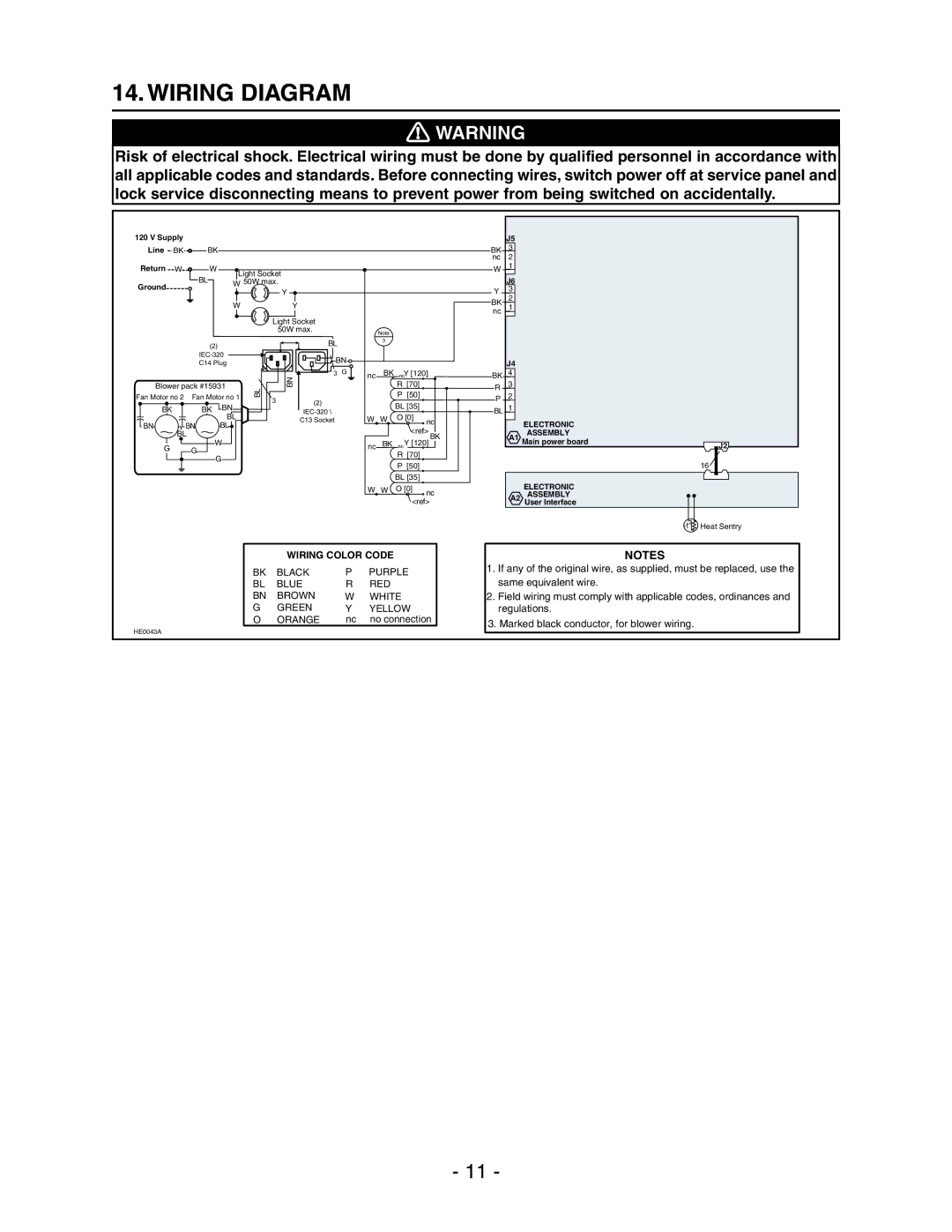
Installation of the Broan Model E662 is straightforward, thanks to comprehensive instructions and mounting templates provided by the manufacturer. Its adaptability to both ducted and ductless configurations offers flexibility, catering to various kitchen setups.
In summary, the Broan Model E662 is a premier choice for those looking to enhance their kitchen's performance and aesthetics. With its powerful ventilation, stylish design, user-friendly technology, and quiet operation, it sets a new standard in range hood excellence. Whether you're a casual cook or a culinary enthusiast, this model ensures that your kitchen remains a pleasant and inviting space.