| Chapter |
LED Codes | 3 |
|
|
In this chapter
•System status LEDs . . . . . . . . . . . . . . . . . . . . . . . . . . . . . . . . . . . . . . . . . . . . . 7
•SFP Gigabit Ethernet LEDs. . . . . . . . . . . . . . . . . . . . . . . . . . . . . . . . . . . . . . . 12
•Out of band management port LEDs. . . . . . . . . . . . . . . . . . . . . . . . . . . . . . . 13
•Out of band management port status LED . . . . . . . . . . . . . . . . . . . . . . . . . . 13
The Mobility RFS6000 Controller has four
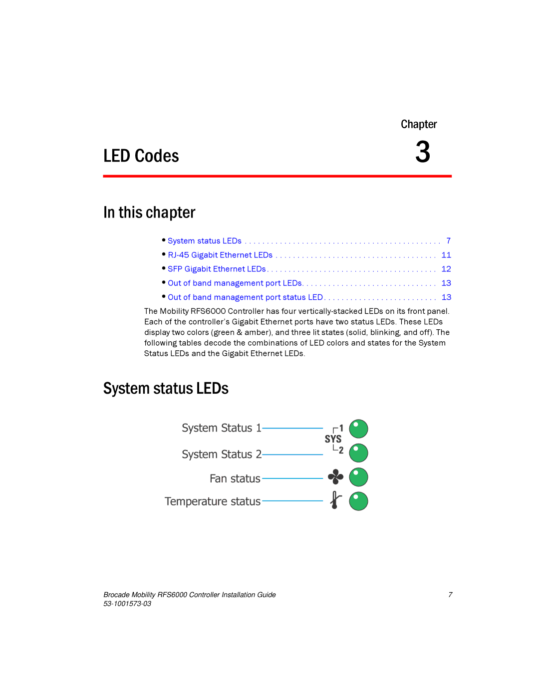
System status LEDs
System Status 1
System Status 2
Fan status
Temperature status![]()
![]()
![]()
Brocade Mobility RFS6000 Controller Installation Guide | 7 |
|