English
APPENDICES
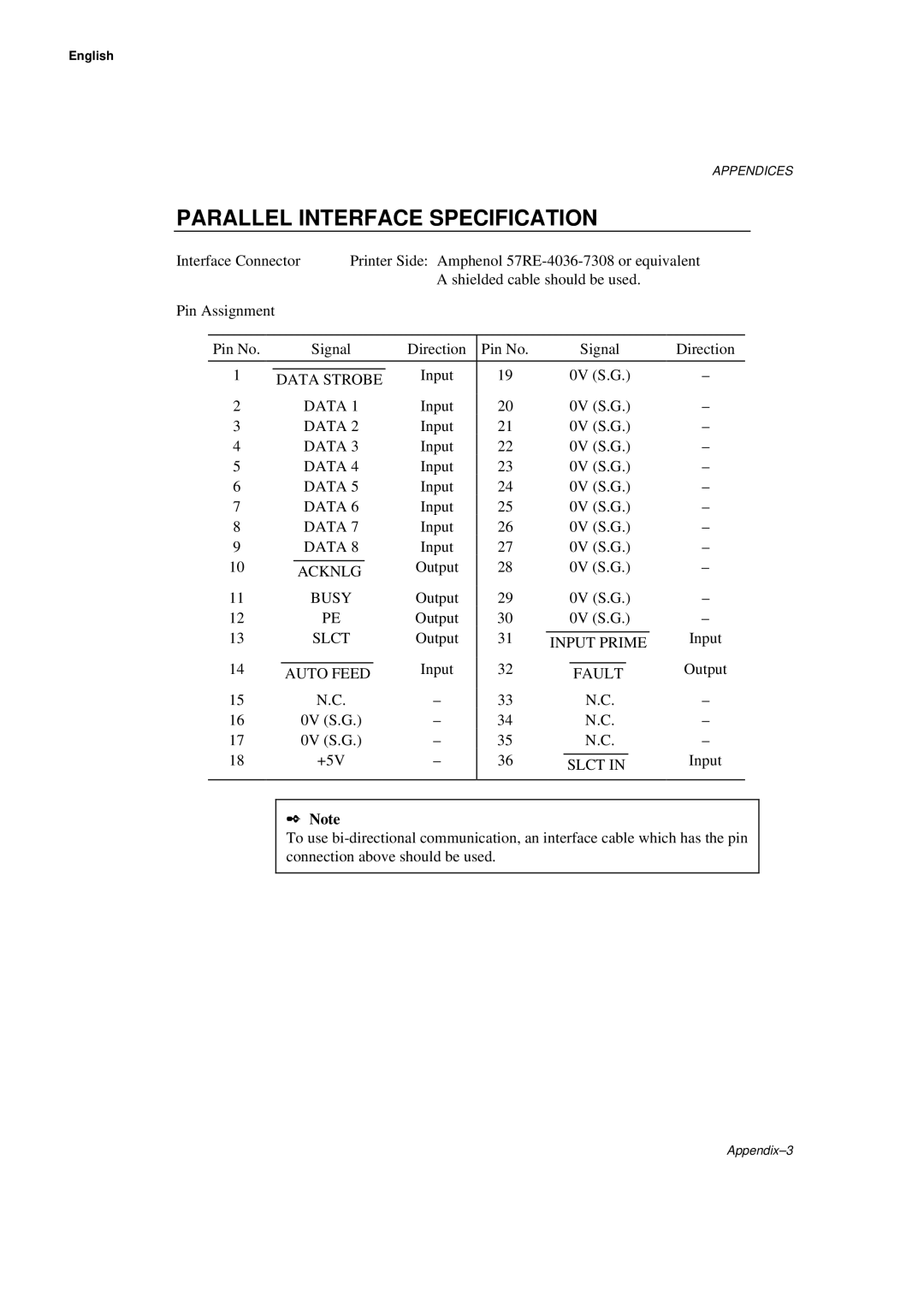
PARALLEL INTERFACE SPECIFICATION
Interface Connector | Printer Side: Amphenol | |||||||||||||||
|
|
|
|
|
|
|
|
| A shielded cable should be used. |
| ||||||
Pin Assignment |
|
|
|
|
|
|
|
|
|
|
|
|
|
| ||
|
|
|
|
|
|
|
|
|
|
|
|
|
|
|
|
|
| Pin No. |
|
|
| Signal | Direction | Pin No. |
|
| Signal | Direction | |||||
|
|
|
|
|
|
|
|
|
|
|
|
|
|
|
|
|
1 |
|
|
|
|
|
|
| Input | 19 |
| 0V (S.G.) | – | ||||
| DATA STROBE | |||||||||||||||
|
|
|
|
|
|
|
|
|
|
| ||||||
2 |
|
|
|
| DATA 1 | Input | 20 |
| 0V (S.G.) | – | ||||||
3 |
|
|
|
| DATA 2 | Input | 21 |
| 0V (S.G.) | – | ||||||
4 |
|
|
|
| DATA 3 | Input | 22 |
| 0V (S.G.) | – | ||||||
5 |
|
|
|
| DATA 4 | Input | 23 |
| 0V (S.G.) | – | ||||||
6 |
|
|
|
| DATA 5 | Input | 24 |
| 0V (S.G.) | – | ||||||
7 |
|
|
|
| DATA 6 | Input | 25 |
| 0V (S.G.) | – | ||||||
8 |
|
|
|
| DATA 7 | Input | 26 |
| 0V (S.G.) | – | ||||||
9 |
|
|
|
| DATA 8 | Input | 27 |
| 0V (S.G.) | – | ||||||
10 |
|
|
|
|
|
|
| Output | 28 |
| 0V (S.G.) | – | ||||
|
|
| ACKNLG | |||||||||||||
|
|
|
|
|
|
|
|
|
|
|
|
| ||||
11 |
|
|
|
| BUSY | Output | 29 |
| 0V (S.G.) | – | ||||||
12 |
|
|
|
| PE | Output | 30 |
| 0V (S.G.) | – | ||||||
13 |
|
|
|
| SLCT | Output | 31 |
|
|
|
|
| Input | |||
|
|
|
| INPUT PRIME | ||||||||||||
|
|
|
|
|
|
|
|
|
|
|
| |||||
14 |
|
|
|
|
|
|
| Input | 32 |
|
|
|
|
| Output | |
|
| AUTO FEED |
|
| FAULT | |||||||||||
|
|
|
|
|
|
|
|
| ||||||||
15 |
|
|
|
| N.C. | – | 33 |
|
| N.C. | – | |||||
16 |
|
|
|
| 0V (S.G.) | – | 34 |
|
| N.C. | – | |||||
17 |
|
|
|
| 0V (S.G.) | – | 35 |
|
| N.C. | – | |||||
18 |
|
|
|
| +5V | – | 36 |
|
|
|
|
| Input | |||
|
|
|
|
| SLCT IN | |||||||||||
|
|
|
|
|
|
|
|
|
|
|
|
| ||||
|
|
|
|
|
|
|
|
|
|
|
|
|
|
|
|
|
✒Note
To use