127A
Check Charge
The 127A units may be charged in high- or
Unit is factory charged for 15ft (4.57 m) of lineset. Adjust charge by adding or removing 0.6 oz/ft of 3/8 liquid line above or below 15ft (4.57 m) respectively.
For standard refrigerant line lengths (80 ft/24.38 m or less), allow system to operate in cooling mode at least 15 minutes. If conditions are favorable, check system charge by subcooling method. If any adjustment is necessary, adjust charge slowly and allow system to operate for 15 minutes to stabilize before declaring a properly charged system.
If the indoor temperature is above 80_F (26.67_C), and the outdoor temperature is in the favorable range, adjust system charge by weight based on line length and allow the indoor temperature to drop to 80_F (26.67_C) before attempting to check system charge by subcooling method as described above.
If the indoor temperature is below 70_F (21.11_C), or the outdoor temperature is not in the favorable range, adjust charge for line set length above or below 15ft (4.57 m) only. Charge level should then be appropriate for the system to achieve rated capacity. The charge level could then be checked at another time when the both indoor and outdoor temperatures are in a more favorable range.
NOTE: If line length is beyond 80 ft (24.38 m) or greater than 20 ft (6.10 m) vertical separation, See Long Line Guideline for special charging requirements.
Final Checks
IMPORTANT: Before leaving job, be sure to do the following:
1.Ensure that all wiring is routed away from tubing and sheet metal edges to prevent
2.Ensure that all wiring and tubing is secure in unit before adding panels and covers. Securely fasten all panels and covers.
3.Tighten service valve stem caps to
4.Leave Owner’s Manual with owner. Explain system opera- tion and periodic maintenance requirements outlined in manual.
5.Fill out Dealer Installation Checklist and place in customer file.
TROUBLESHOOTING
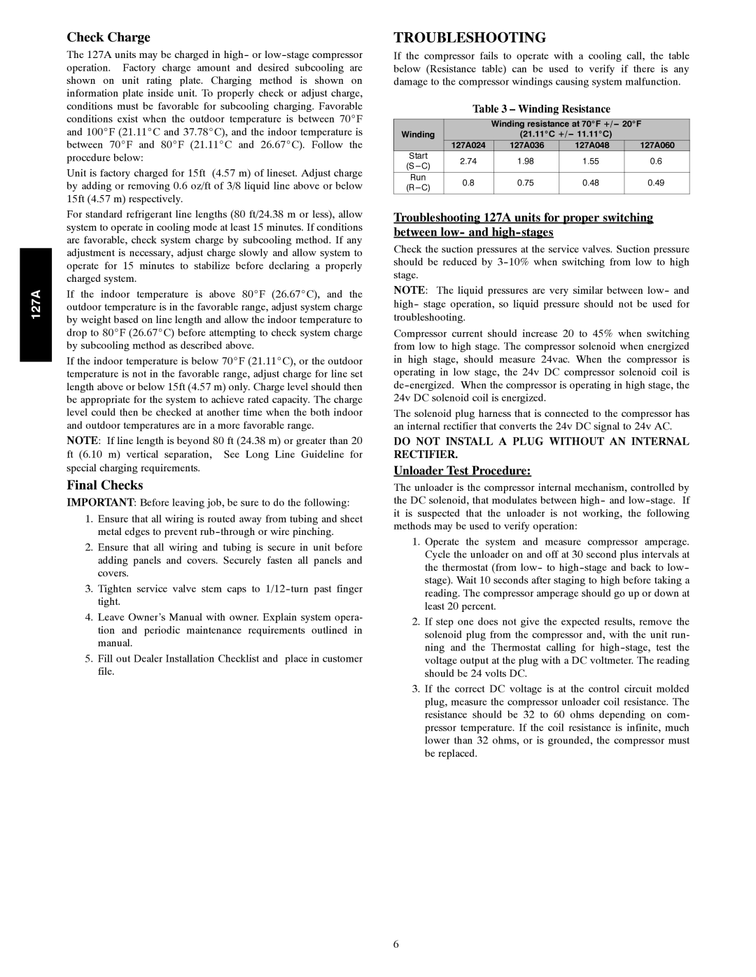
If the compressor fails to operate with a cooling call, the table below (Resistance table) can be used to verify if there is any damage to the compressor windings causing system malfunction.
Table 3 – Winding Resistance
|
| Winding resistance at 70_F | |||
Winding |
| (21.11_C |
| ||
| 127A024 | 127A036 | 127A048 | 127A060 | |
Start | 2.74 | 1.98 | 1.55 | 0.6 | |
(S | |||||
|
|
|
| ||
Run | 0.8 | 0.75 | 0.48 | 0.49 | |
|
|
|
| ||
Troubleshooting 127A units for proper switching between low- and
Check the suction pressures at the service valves. Suction pressure should be reduced by
NOTE: The liquid pressures are very similar between low- and high- stage operation, so liquid pressure should not be used for troubleshooting.
Compressor current should increase 20 to 45% when switching from low to high stage. The compressor solenoid when energized in high stage, should measure 24vac. When the compressor is operating in low stage, the 24v DC compressor solenoid coil is
The solenoid plug harness that is connected to the compressor has an internal rectifier that converts the 24v DC signal to 24v AC.
DO NOT INSTALL A PLUG WITHOUT AN INTERNAL RECTIFIER.
Unloader Test Procedure:
The unloader is the compressor internal mechanism, controlled by the DC solenoid, that modulates between high- and
1.Operate the system and measure compressor amperage. Cycle the unloader on and off at 30 second plus intervals at the thermostat (from low- to
2.If step one does not give the expected results, remove the solenoid plug from the compressor and, with the unit run- ning and the Thermostat calling for
3.If the correct DC voltage is at the control circuit molded plug, measure the compressor unloader coil resistance. The resistance should be 32 to 60 ohms depending on com- pressor temperature. If the coil resistance is infinite, much lower than 32 ohms, or is grounded, the compressor must be replaced.
6