Table 5 –
(Winding Resistance at 70_F ± 20_ / 21.11_C ± 11.11_C)
Winding | 187A024 | 187A036 | 187A048 | 187A060 |
Start | 2.74 | 1.98 | 1.55 | 0.74 |
Run | 0.80 | 0.75 | 0.48 | 0.36 |
|
|
|
|
|
Winding | 180A024 | 180A036 | 180A048 | 180A060 |
Start | 1.40 | 1.29 | 1.52 | 0.60 |
Run | 1.32 | 0.89 | 0.64 | 0.49 |
MAJOR COMPONENTS
2-Stage Control
The
-Low- and
-Outdoor fan motor operation
-Low ambient cooling
-Crankcase heater operation
-Compressor external protection
-Pressure switch monitoring
-Time delays
-On 187A models, start relay and capacitor
Field Connections
On 187A models with
All 180A models are part of a complete Evolution communicating system and use only the ABCD connections on the circuit board. The 180A must be controlled using an Evolution User Interface for proper equipment staging and operation
2-Stage Compressor
The
Compressor Internal Relief
The compressor is protected by an internal pressure relief (IPR) which relieves discharge gas into compressor shell when differential between suction and discharge pressures exceeds 500 - 550 psi on 187A models and 550 - 625 psi on 180A models. The compressor is also protected by an internal overload attached to motor windings.
Compressor Control Contactors
The contactor(s) have a 24 volt coil. The electronic control board controls the operation of the appropriate contactors.
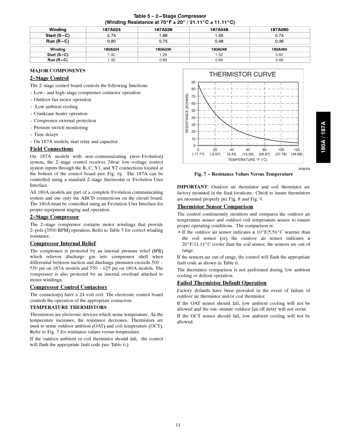
TEMPERATURE THERMISTORS
Thermistors are electronic devices which sense temperature. As the temperature increases, the resistance decreases. Thermistors are used to sense outdoor ambient (OAT) and coil temperature (OCT). Refer to Fig. 7 for resistance values versus temperature.
If the outdoor ambient or coil thermistor should fail, the control will flash the appropriate fault code (see Table 6.)
THERMISTOR CURVE
| 90 | |
(KOHMS) | 80 | |
70 | ||
| ||
| 60 | |
RESISTANCE | 50 | |
20 | ||
| 40 | |
| 30 | |
| 10 | |
| 0 |
0 | 20 | 40 | 60 | 80 | 100 | 120 |
(4.44) | (15.56) | (26.67) | (37.78) | (48.89) | ||
|
| TEMPERATURE °F (°C) |
|
| ||
A08054
Fig. 7 - Resistance Values Versus Temperature
IMPORTANT: Outdoor air thermistor and coil thermistor are factory mounted in the final locations. Check to insure thermistors are mounted properly per Fig. 8 and Fig. 9.
Thermistor Sensor Comparison
The control continuously monitors and compares the outdoor air temperature sensor and outdoor coil temperature sensor to ensure proper operating conditions. The comparison is:
SIf the outdoor air sensor indicates ≥ 10_F/5.56_C warmer than the coil sensor (or) the outdoor air sensor indicates ≥ 20_F/11.11_C cooler than the coil sensor, the sensors are out of range.
If the sensors are out of range, the control will flash the appropriate fault code as shown in Table 6.
The thermistor comparison is not performed during low ambient cooling or defrost operation.
Failed Thermistor Default Operation
Factory defaults have been provided in the event of failure of outdoor air thermistor and/or coil thermistor.
If the OAT sensor should fail, low ambient cooling will not be allowed and the
If the OCT sensor should fail, low ambient cooling will not be allowed.
180A / 187A
11